DESCRIPTION OF BLOCK
2. DESCRIPTION OF BLOCK
1. Operation of Block
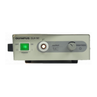
Operation of the CLH-SC is described using a block diagram (2-2).
Power supplied on the power cable is applied to the interlock switch through two fuses. The power
passing through the interlock switch is applied to the power switch on the front panel and is then sent
to the terminal block. The power is returned from the live side to the terminal block through the
thermo-fuse provided on the side of the power switch. The thermo-fuse operates to stop all functions
and avoid a danger when the fan stops, the air duct is blocked and the main body is abnormally heated.
The nominal operating temperature of the thermo-fuse is 117°C.
The power of 15 VAC for lighting the lamp is decreased by the transformer and is applied to the
secondary side to supply power to the lamp. The DC fan is supplied with the power that is obtained by
rectifying the lamp power supply by a diode and then smoothing by a capacitor. The transformer is
provided with a thermo-fuse of 135°C to prevent overheat, but the fuse can not be replaced. If the fuse
blows, the transformer must be replaced. This power supply circuit is provided on the UPCH10 board.
A branch from the transformer to the lamp socket, a fan rectifying/smoothing circuit and two
connectors to supply power to the fan are provided.
2-1