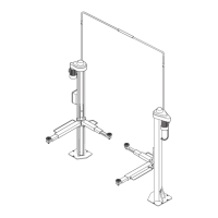
Fig.59-Abb.59
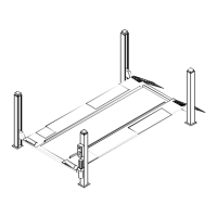
Fig.60-Abb.60
ALLACCIAMENTOIMPIANTOELETTRICO
I
ATTENZIONE
Leoperazionisottoelencatedevonoessereeseguite
dapersonalequalificato.
1)Primadelcollegamentoelettricoverificareche:
·
l’impiantodialimentazionealsollevatoresiadotatodelleprotezioni
previstedallenormevigentinelpaeseincuivieneinstallato.
·
lalineadialimentazioneabbialaseguentesezione:
Tensionesollevatore400Vtrifase:............minimo2,5mm2
Tensionesollevatore230Vtrifase:............minimo4mm2
Tensionesollevatore230Vmonofase:......minimo6mm2
·
leoscillazioniditensionerientrinonelcampoditolleranzaprevisto
dallespecifiche.
2)Eseguirel’allacciamentodipotenzaedicomandoallamorsettiera
delquadro,inserendoilcavonellacassettapassandodaunodeidue
foripredispostieseguendoloschemadell’impiantoelettricocomenelle
pagine9e10.
I
ATTENZIONE
Ilcostruttorefornisceilponteconmotoretrifase,
predispostoperilfunzionamentoa400V.
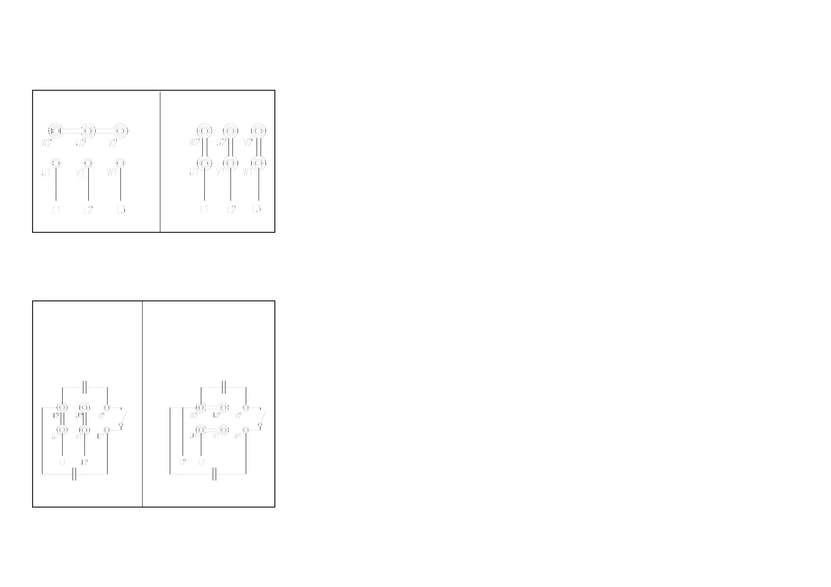
Fig.59Collegamentimotoremonofase.
3)Chiudereilcoperchiodelquadroelettrico,ruotarel’interrutoregene
-
rale(IG,Fig.60)inposizione1,premereilpulsantedisalita(rif.P1,
Fig.61)e,incasodidiscesadeicarrelli,invertiretraloro2fasidell’ali
-
mentazione.
4)Controllareilcorrettofunzionamentodeifinecorsadiestremitàcolon
-
napremendolimanualmente.
CONNECTIONTOPOWERSUPPLY
I
WARNING
Thefollowingoperationsmustbeperformedbyqua
-
lifiedpersonnelonly.
1)Beforeconnectingpowersupply,checkthat:
·
theelectricalsystemintheworkshopisequippedwiththeprotective
devicesenvisagedbynationalsafetystandards.
·
thepowerlineissuitablysized:
Liftrackvoltage:400V.............................Min.size:2.5mm2
Liftrackvoltage:230V.............................Min.size:4mm2
Liftrackvoltage:230VSingle-phase:......Min.size:6mm2
·
voltagefluctuationsarewithinthetolerancespecifiedinthespecifica
-
tions.
2)Usetheelectricalplantwiringplaninpages9and10whenconnec
-
tingtopowersupplyandpanelterminals.
Openthecontrolpanelcoverandrouteinthewiresthroughoneofthe
cableinletholesalreadypresent.
I
WARNING
Themanufacturersupplytheliftrackwithathree-
phasemotorsetto400v.
Fig.59 Single-phasemotorconnections
3)Closetheelectricpanel,setthemasterswitch(ref“IG”infig.60)to
position1,thenpresstheLIFTbutton(ref.P1inFig.61);ifthecarriages
descend,invert2ofthepowerlines.
4)Checkthatthepostlimitswitchesoperatecorrectlybypressingma
-
nually.
50
400V 230V
RotazioneA
RotationA
RotationA
DrehrichtungA
RotaciònA
RotazioneB
RotationB
RotationB
DrehrichtungB
RotaciònB