CAP.4 INSTALLAZIONE
QUE STE OPE RA ZIO NI SONO DI COM PE TEN ZA
ESCLU SI VA DEI TEC NI CI SPE CIA LIZ ZA TI IN CA RI
-
CA TI DAL CO STRUT TO RE O DAI RI VEN DI TO RI
AU TO RIZ ZA TI .
SE EF FET TUA TE DA AL TRE PER SO NE POS SO
-
NO CREA RE SI TUA ZIO NI DI PE RI CO LO E CAU
-
SA RE GRA VI DAN NI ALLE PER SO NE E/O AL
SOL LE VA TO RE.
VERIFICA DEI REQUISITI PER L’INSTALLAZIONE
VERIFICA DI IDONEITA’ DEL LOCALE PRESCELTO.
Il sol le va to re è co strui to per l’im pie go in lo ca li chiu si e ri pa ra ti. Il
luo go pre scel to non deve es se re vi ci no a la vag gi, a po sti di ver ni -
cia tu ra, a de po si ti di sol ven ti o ver ni ci, a lo ca li con la vo ra zio ni che
pos so no crea re at mo sfe re esplo si ve.
VERIFICA DI IDONEITA’ DELLE DIMENSIONI DEL LOCALE E
DELLE DISTANZE DI SICUREZZA.
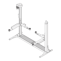
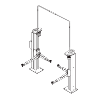
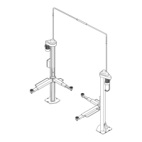
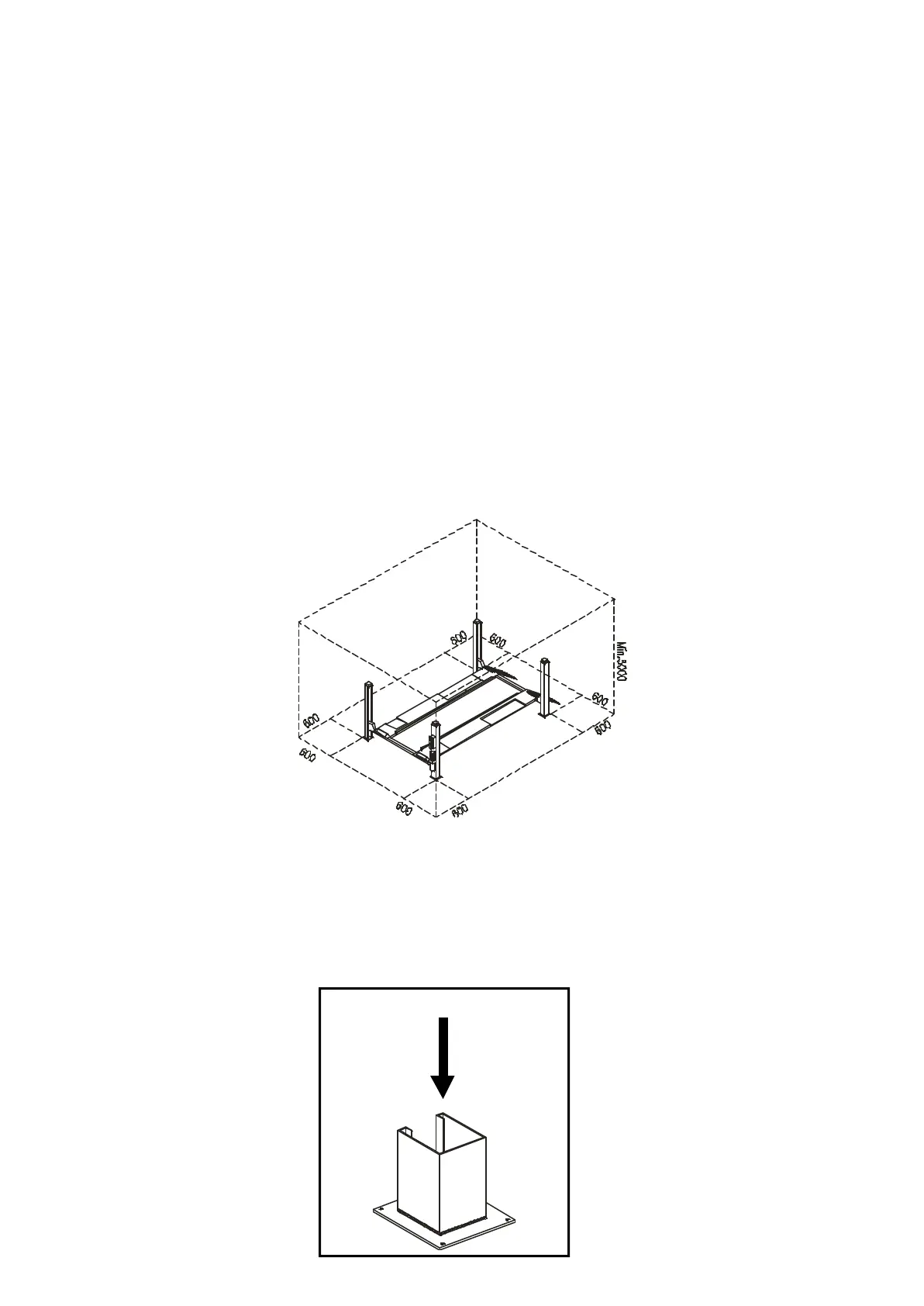
Il sol le va to re deve es se re in stal la to ri spet tan do le di stan ze di si cu -
rez za da muri,co lon ne, al tre mac chi ne, ecc... come in di ca te in Fi -
gu ra 35 e se con do le even tua li pre scri zio ni del la le gi sla zio ne vi -
gen te nel luo go di in stal la zio ne.
Oc cor re la scia re co mun que uno spa zio li be ro mi ni mo di 500 mm
tra ogni par te mo bi le del sol le va to re e del vei co lo sol le va to e le al -
tre strut tu re fis se o mo bi li piu’ vi ci ne.
Ve ri fi ca re in par ti co la re:
- al tez za:mi ni mo 5000 mm
(con si de ra re l’al tez za dei vei co li da sol le va re),
- di stan za dai muri mi ni mo 600 mm,
- spa zi per la vo ra re mi ni mo 600 mm,
- spa zi per la PO STA ZIO NE DI CO MAN DO,
- spa zi per la ma nu ten zio ne,
- ac ces si,
- vie di fuga in caso di emer gen za,
- po si zio ne re la ti va alle al tre mac chi ne,
- orien ta men to fun zio na le del sol le va to re,
- pos si bi li tà di rea liz za re l’al lac cia men to
elet tri co.
Fig.35 Di stan ze di si cu rez za
Fig.35 Sa fe ty di stan ces
ILLUMINAZIONE
Tut te le zone del la mac chi na de vo no es se re il lu mi na te in modo
uni for me e suf fi cien te per ga ran ti re le ope ra zio ni di re go la zio ne e
ma nu ten zio ne pre vi ste nel ma nua le, evi tan do zone d’om bra, ri fles -
si, ab ba glia men to e af fa ti ca men to del la vi sta.
L’il lu mi na zio ne deve es se re rea liz za ta in ac cor do con la nor ma ti va
vi gen te nel luo go di in stal la zio ne (a cura dell’in stal la to re dell’im -
pian to di il lu mi na zio ne).
PAVIMENTO
Il sol le va to re deve es se re in stal la to su pla tea
oriz zon ta le di ade gua ta re si sten za.
La pla tea e le fon da zio ni de vo no es se re ido nee
a so ste ne re i va lo ri mas si mi di sol le ci ta zio ne
che il sol le va to re eser ci ta sul ter re no nel le piu’
sfa vo re vo li con di zio ni di eser ci zio: la pres sio ne
spe ci fi ca eser ci ta ta dal sol le va to re se con do l’u
-
so pre vi sto è di cir ca 5 Kg/cm (Fig.36).
- Ca ri co ver ti ca le: 1850 Kg
- Ta glio: tra scu ra bi le
Il pa vi men to deve inol tre es se re pia no e ben li
-
vel la to (Max. 10 mm sul li vel la men to).
Fig.36
Ca ri chi sul le fon da zio ni
CHAPTER 4 INSTALLATION
THE FOL LOWING OPE RA TIONS MUST BE PER
-
FOR MED EX CLU SI VELY BY SPE CIA LI SED TECH
-
NI CAL STAFF WITH AUT HO RI SA TION FROM THE
MA NU FAC TU RER OR LI CEN SED DEA LER.
IF THE SE OPE RA TIONS ARE PER FOR MED BY
OT HER PER SONS, SE RIOUS PER SO NAL IN JU RY
AND/OR IR RE PA RA BLE DA MA GE TO THE LIFT
UNIT MAY RE SULT.
INSTALLATION REQUIREMENT CHECK
MAKE SURE THAT THE INTENDED PLACE OF INSTALLATION
IS SUITABLE.
The lift is de si gned for in stal la tion in en clo sed areas sui ta bly pro -
tected from weat her. The pla ce of in stal la tion must be well clear of
areas in which was hing or pain ting work is per for med, and away
from sol vent or paint sto ra ge areas or areas, whe re the re is a risk
of po ten ti al ly ex plo si ve at mo sphe re.
CHECK OF ROOM SUITABILITY AND SAFETY CLEARANCES.
The lift must be in stal led in com plian ce with the clea ran ces betwe
-
en walls, pil lars, ot her ma chi nes, etc. in di ca ted in Fi gu re 35 and in
com plian ce with any law re qui re ments in the coun try of in stal la tion.
In any event, the re must be a mi ni mum clea ran ce of 500 mm
betwe en all mo vab le parts of the lift and the vehic le itself and the
nea rest fixed or mo bi le struc tu res in the work shop.
Check:
- height: 5000 mm min.
(cal cu la te also the height of the vehi
-
cles you in tend to lift),
- di stan ce from walls: 600 mm min.,
- wor king spa ce: 600 mm min.,
- CON TROL PO SI TION area,
- main te nan ce area,
- ac cess,
- es cape rou tes for emer gency si tua -
tions,
- po si tion in re la tion to ot her ma chi -
nes,
- ra tio nal orien ta tion of the lift,
- pos si bi li ty of elec tri cal con nec tion.
LIGHTING
All parts of the ma chi ne must be uni form ly lit with suf fi cient light to
make sure that the adjustment and main te nan ce ope ra tions spe ci -
fied in the ma nual can be per for med sa fely, and wit hout areas of
shadow, re flected light, gla re and avoi ding all si tua tions that could
give rise to eye fa ti gue.
The lighting must be in stal led in ac cor dan ce with the laws in for ce
in the pla ce of in stal la tion (re spon si bi li ty lies with the lighting
equipment fit ter).
FLOOR
The lift must be in stal led on a ho ri zon tal plat -
form with sui tab le load ca pa city.
The plat form and the foun da tions must be sui
-
tab le to re sist the ma xi mum stress va lues that
the lift can transmit to the ground en vi sa ging
the worst ope ra ting con di tions: spe ci fic ground
pres su re exer ted by the lift in the pre scri bed
con di tions of use is ap proxi ma tely 5 kg/cm
(Fig.36).
- Ver ti cal load: 1850 kg
- Shear for ce: ne gli gib le
The flo or must be flat and wit hout gra dients
(ma xi mum of 10 mm to le ran ce)
Fig.36
Loads on foun da tions
22
P max.
1850 Kg.
 Loading...