MONTAGGIO RAMPE DI SALITA E ARRESTI FERMARUOTA
Le ram pe di sa li ta (pos.41, Fig.56) e gli ar re sti fer ma ru o ta (42) pos
-
so no es se re mon ta ti da ambo le par ti del le pe da ne (7-8) se con do
le ne ces si tà dell’utilizzatore. Pro ce de re al mon tag gio in ca stran do
sul lato de si de ra to le ram pe di sa li ta (41) e fis sa re tra mi te viti TE
M10x25 (43), ro set te Ø11 x 30(44) e dadi M10 (45) gli ar re sti fer -
ma ru o ta (42) sul lato op po sto.
Fig.56 Fis sag gio ram pe e bloc cag gi ru o te
REGISTRAZIONE FUNI
Fig.57: sa li re sul pon te con un’au to vet tu ra.
Po si zio nar si all’al tez za mas si ma e ve ri fi ca re che i 4 mar tel-let ti (32)
sia no al log gia ti den tro le aso le del le aste di si cu rez za (12).
Ve ri fi ca re che la di stan za tra i mar tel let ti (32) e le aso le del le aste
di si cu rez za (12) sul le 4 co lon ne (1- 2- 3-4) sia 20mm mi ni mo dal
suo ap pog gio (fig.57) una mi su ra in fe rio re non da reb be il tem po
alla si cu rez za ri ruo ta re ri ma nen do ag gan cia ta all’a sta.
Se ne ces sa rio pro ce de re al li vel la men to agen do sui dadi (20) dei
ter mi na li (19) del le funi (33)e re go lan do il mi cro in ter rut to re fi ne cor -
sa.
A re gi stra zio ne ul ti ma ta bloc ca re con i con tro da di (35).
IMPORTANTE: Questa operazione di registrazione é da
ripeter-si dopo 1 o 2 settimane dalla messa in servizio del
sollevatore.
Fig.57 Re gi stra zio ne funi
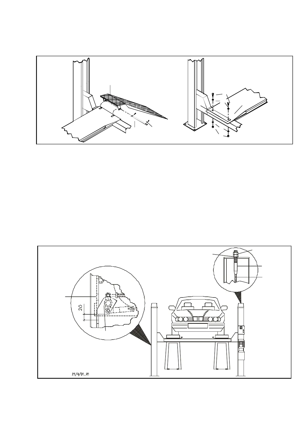
INSTALLING THE VEHICLE RAMPS AND THE WHEEL STOPS
The ve hi cle ramps (pos.41, fig.56) and the whe el stops (42) can be
fit ted on eit her end of plat forms (7 - 8) ac cor ding to the user’s re
-
qui re ments. Fit the ramps (41) by slot ting them into the plat forms
on the re qui red end and then fix the whe el stops (42) on the op po -
si te end using M10 x 25 H.H. screws (43), 11 x 30 wa shers (44)
and M10 nuts (45).
Fig.56 Se cu ring the ve hi cle ramps and whe el stops
ADJU STING THE LIF TING CABLES
Fig. 57: drive a vehic le onto the lift.
Rai se the lift to the ma xi mum height and check if the four wed ges
(32) are fit ted in si de the slots of the sa fe ty rods (12).
Check if the di stan ce betwe en the wed ges (32) and the slots of the
sa fe ty rods (12) on the 4 posts (1- 2- 3-4) is at least 20 mm from the
sup port (fig. 57); a lower va lue would not al low the sa fe ty de vi ce to
ro ta te, and it would stay at ta ched to the rod.
If ne ces sa ry, le vel the unit by adju sting the nuts (20) on the ter mi -
nals (19) of the cables (33) and the li mit mi cro switch.
When the adjustment is com ple ted, lock with the lock nuts (35).
IMPORTANT: This adjustment must be repeated 1 or 2 weeks
after setting up the lift.
Fig.57 Adju sting the lift cables
31
45
43
41
44
44
42
48
47
12
32
20
35
19
33
 Loading...