ARTWORK/PRODUCT ART/
DWGS/START HERE ARROW
START HERE
ARTWORK/PRODUCT ART/
DWGS/START HERE ARROW
ARTWORK/PRODUCT ART/
DWGS/START HERE ARROW
ARTWORK/PRODUCT ART/
DWGS/START HERE ARROW
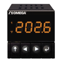
CND3 Series Temperature Controller
Warning
DANGER! Caution! Electric Shock! When the power is on, DO NOT touch the AC terminals in case
an electric shock may occur. Make sure the power is disconnected when you check the input power
supply.
1. Prevent dust or metallic debris from falling into the controller and cause malfunctions. DO NOT modify or uninstall
the controller.
2. CND3 controller is an open-type device. Make sure it is installed in an enclosure free of dust and humidity in case of
an electric shock.
3. Wait for one minute after the power is switched off to allow the capacitor to discharge. DO NOT touch the internal
wiring within this period of time.
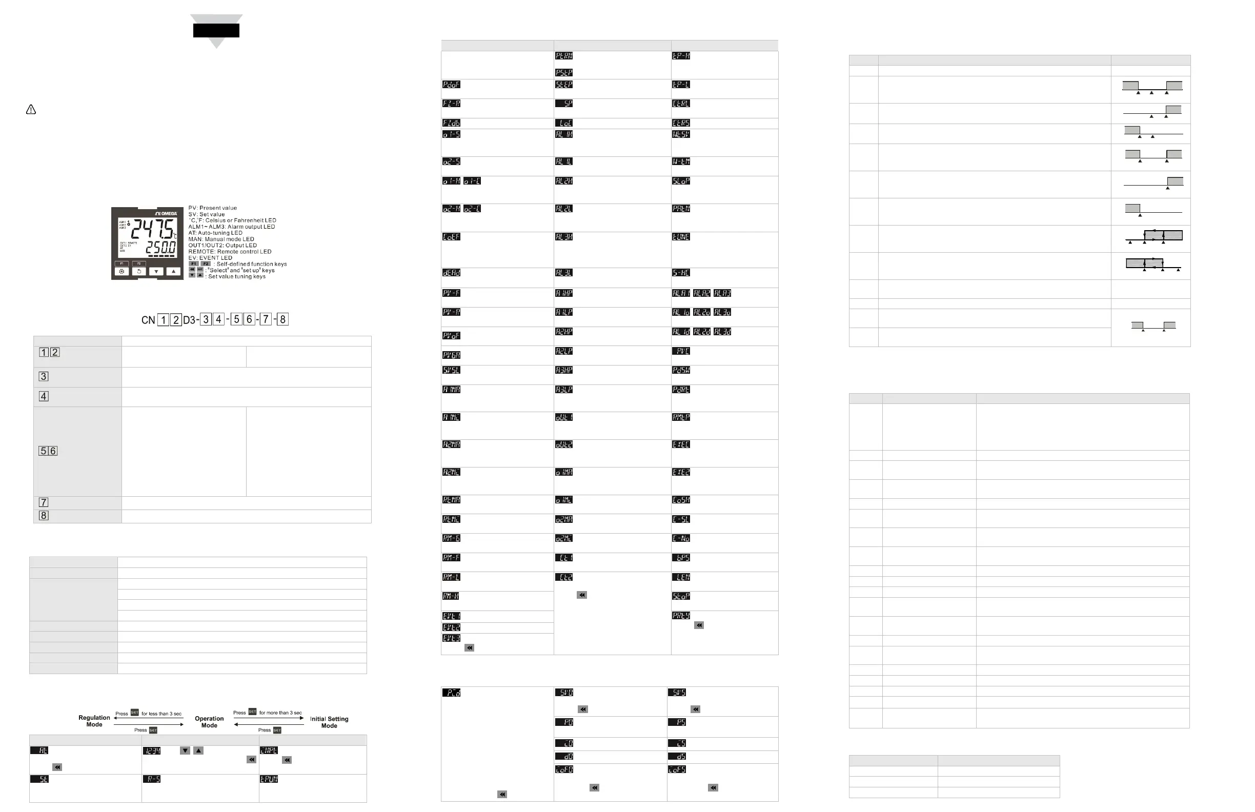
Display, LED & Keys
Ordering Information
Series Omega CND3 series temperature controller
Panel size
04: 1/4 DIN
08: 1/8 DIN
16: 1/16 DIN
Output 1
R: Relay M: Linear mA
S: Voltage Pulse L: Linear voltage
Output 2
R: Relay M: Linear mA blank: none
S: Voltage Pulse L: Linear voltage
Option 1
1U: 1 User input
2U: 2 User inputs
1C: 1 CT input
2C: 2 CT inputs
RT: Retransmission output
RS: Remote Setup Input
UC: User input + CT input
RR: Retrainsmission + Remote
Setup input
UR: User input + Retransmission
output
US: User input + Remote Setup
input
CR: CT input + Retrainsmission
output
CS: CT input + Remote Setup input
blank: none
Option 2
CM: RS-485 Communication blank: none
Power
AC: AC 100 to 240V DC: DC 24V
Specifications
Input power supply AC 100 to 240 V, 50/60Hz, DC 24 V ±10%
Display method LCD. Present temperature: yellow, Set temperature: green
Input sensors
Thermocouple: K, J, T, E, N, R, S, B, L, U, TXK
Platinum RTD: Pt100, JPt100
Resistance: Cu50, Ni120
Analog input: 0 to 5 V, 0 to 10 V, 0 to 20 mA, 4 to 20 mA, 0 to 50 mV
Control modes PID, PID programmable, Fuzzy, Self-tuning, manual, ON/OFF
Display accuracy 0 or 1 digit to the right of the decimal point
Sampling rate Analog input: 0.1s, Thermocouple or platinum RTD: 0.1s
Ambient temperature 0 to +50°C
Ambient humidity 35 to 80% RH (non-condensing)
Parameters Operation
Regulation Mode Operation Mode Initial Setting Mode
Auto-tuning (Set in PID
control and RUN mode)
Press
Use to set up target
temperature Press
Set up input type
Press
Self-tuning switch (set
when in PID control and the
TUNE parameter = ST)
Control loop RUN or
STOP
Set up temperature unit
(not displayed when in analog
input)
Regulation Mode Operation Mode Initial Setting Mode
Select the n
th
(n = 0 ~ 5)
PID. When n = AUTO, PID is
auto-selected.
Set up start pattern (when in
PID programmable control and
)
Set up upper temperature
limit
Set up PID control offset
Set up start step (when in
programmable control)
Set up lower temperature
limit
Set up Fuzzy gain value
Set up the position of
decimal point
Select control modes
Set up Fuzzy Deadband Lock the keys Select SV control modes
Adjust Output 1 hysteresis
(when in ON/OFF control)
Set up upper limit of Alarm 1
Set up waiting
temperature (when in
programmable control)
Adjust Output 2 hysteresis
(when in ON/OFF control)
Set up lower limit of Alarm 1
Set up waiting time (when
in programmable control)
Control cycle for
Output 1 (except in ON/OFF
control)
Set up upper limit of Alarm 2
Set up start slope (when
in programmable control)
Control cycle for
Output 2
(except in ON/OFF control)
Set up lower limit of Alarm 2 Select pattern to be edited
Ratio of Output 1 against
Output 2 when in dual output
control (set when in PID and dual
output control)
Set up upper limit of Alarm 3 Select AT or ST
Set up deadband
(when in dual output)
Set up lower limit of Alarm 3
Select heating, cooling or
dual output heating and cooling
Set up input filter factor
Record highest
temperature of Alarm 1
Set up Alarm
1 mode
Set up input filter range
Record lowest
temperature of Alarm 1
Set up Alarm
1 options
Adjust input compensation
Record highest
temperature of Alarm 2
Set up Alarm
1 delay
Adjust input gain
Record lowest
temperature of Alarm 2
PV color change
Set up rising slope (when
CRTS = SLOP)
Record highest
temperature of Alarm 3
2PID Switch temperature
Adjust upper limit
compensation for analog Output
1*
Record lowest
temperature of Alarm 3
2PID Reset temperature
Adjust lower limit
compensation for analog Output
1*
Display and adjust Output 1
volume
Set up Remote type
Adjust upper limit
compensation for analog Output
2*
Display and adjust Output 2
volume
Select auxiliary function 1
Adjust lower limit
compensation for analog Output
2*
Set up percentage of upper
limit for Output 1
Select auxiliary function 2
Adjust upper limit
compensation for Retransmission*
Set up percentage of lower
limit for Output 1
Enable/disable
communication write-in
Adjust lower limit
compensation for Retransmission*
Set up percentage of upper
limit for Output 2
Select ASCII or RTU
format
Adjust Remote gain
Set up percentage of lower
limit for Output 2
Set up communication
address
Adjust Remote
compensation
Display current measured at
CT1
Set up baudrate
Remote lower limit
adjustment
Display current measured at
CT2
Press to return to set up
target
temperature
Set up data length
Remote higher limit
adjustment
Set up stop bit
Set up EVENT1 function
Set up parity bit
Press to return to set up
input type
Set up EVENT2 function
Set up EVENT3 function
Press to return to auto-tuning
*1 scale = 2μA; 1scale = 1mV
PID mode: Any of the 6 PID groups can be selected. When n = AUTO, the program will automatically select
the PID group that is the closest to the target temperature.
Select the n
th
PID (n = 0 ~
5)
Press 0 ~ 5
th
PID
Set up the 0
th
PID
temperature value
Press
Set up the 5
th
PID
temperature value
Press
Set up the 0
th
proportional
band value
Set up the 5
th
proportional
band value
Set up the 0
th
Ti value Set up the 5
th
Ti value
Set up the 0
th
Td value Set up the 5
th
Td value
Set up the 0
th
PID integral
deviation
Press to return to PID
deviation
Set up the 5
th
PID integral
deviation
Press to return to PID
deviation
Alarm Outputs
CND3 offers 3 alarm outputs, and each alarm output has 20 alarm modes to choose from in the initial setting mode.
When the target temperature exceeds or falls below the set point, the alarm output will be enabled.
SV Alarm mode Alarm output operation
0 No alarm
1
Alarm output will be enabled when the temperature reaches upper or
lower limit: The alarm will be enable when the PV exceeds SV + AL-H
or falls below SV – AL-L.
2
Alarm output will be enabled when the temperature reaches the upper
limit: The alarm will be enabled when the PV exceeds SV + AL-H.
ON
OFF
SV SV+(AL-H)
3
Alarm output will be enabled when the temperature reaches the lower
limit: The alarm will be enabled when the PV falls below SV – AL-L.
ON
OFF
SV-(AL-L)
SV
4
Alarm output will be enabled when the temperature reaches the
absolute value of the upper or lower limit: The alarm will be enabled
when the PV exceeds AL-H or falls below AL-L.
ON
OFF
AL-L AL-H
5
Alarm output will be enabled when the temperature reaches the
absolute value of the upper limit: The alarm will be enabled when the
PV exceeds AL-H.
ON
OFF
AL-H
6
Alarm output will be enabled when the temperature reaches the
absolute value of the lower limit: The alarm will be enabled when the
PV falls below AL-L.
ON
OFF
AL-L
7
Upper limit hysteresis alarm: The alarm will be enabled when the PV
exceeds SV + AL-H. The alarm will be disabled when the PV falls
below SV + AL-L.
8
Lower limit hysteresis alarm: The alarm will be enabled when the PV
falls below SV – AL-H. The alarm will be disabled when the PV
exceeds SV – AL-L.
9
Offline alarm: The alarm will be enabled when the input sensor is not
correct or offline.
10 Timing alarm
11
CT1 alarm: The alarm will be enabled when the CT1 value falls below
AL-L or exceeds AL-H.
ON
OFF
AL-L
AL-H
12
CT2 alarm: The alarm will be enabled when the CT2 value falls below
AL-L or exceeds AL-H.
¾ RS485 Communication
CND3 supports baudrate 2,400 to 38,400 bps, Modbus ASCII/RTU protocol, function code 03H and reads
maximum 8 words from the register.
Address Content Definition
1000H Present value (PV)
Measuring unit: 0.1 scale. The following values read mean
error occurs.
8002H: Temperature not yet acquired
8003H: Not connected to sensor
8004H: Incorrect sensor
1001H Set value (SV) Measuring unit: 0.1 scale.
1002H
Upper limit of temp.
range
Cannot exceed the default value
1003H
Lower limit of temp.
range
Cannot fall below the default value
1005H Control mode 0: PID, 1: ON/OFF, 2: Manual, 3: FUZZY
1006H
Heating/cooling control 0: Heating/ Heating, 1: Cooling/ Heating, 2: Heating/cooling, 3:
Cooling/ Cooling
1007H
1
st
heating/cooling control
cycle
0.1 ~ 99.0 sec.
1008H
2
nd
heating/cooling control
cycle
0.1 ~ 99.0 sec.
1009H Proportional band (PB) 0.1 ~ 999.9
100AH Ti value 0 ~ 9,999
100BH Td value 0 ~ 9,999
1012H
Read/write Output 1
volume
Unit: 0.1%, only valid in manual control mode
1013H
Read/write Output 2
volume
Unit: 0.1%, only valid in manual control mode
1016H Regulated temp. value -99.9 ~ +99.9, Unit: 0.1
102AH Read/write LED status
b0: ALM3, b1: ALM2, b2: °F, b3: °C, b4: ALM1, b5: OUT2, b6:
OUT1, b7: AT
102BH Read/write key status b0: Set, b1: Select, b2: Up, b3: Down, 0: Press it
102CH Panel lockup status 0: Normal, 1: Fully locked, 2: SV adjustable
102DH CT value Unit: 0.1A
103BH AT setting
0:OFF(default), 1:ON
103CH Control RUN/STOP
setting
0 : STOP, 1:RUN (default), 2 : END (program), 3 : HOLD
(program)
Panel Cutout
Model Panel cutout ( W × H )
1/16 DIN 45mm × 45mm
1/8 DIN 44.5mm × 91.5mm
1/4 DIN 91mm × 91mm
ON
OFF
SV SV+(AL-L) SV+(AL-H)
ON
OFF
SV-(AL-H) SV-(AL-L) SV
ON
OFF
SV-(AL-L) SV SV+(AL-H)

 Loading...