Do you have a question about the Omega CN616TC1 and is the answer not in the manual?
Provides a detailed overview of the CN616 Series controller's purpose and capabilities.
Lists the key features and functionalities of the CN616 Series controller.
Details the available models of the CN616 Series temperature controllers.
Explains the basic operational modes and behavior of the CN616 controller.
Describes the RS-232 communication capabilities and setup for the CN616 controller.
Illustrates the necessary cable connections for RS-232 communication.
Defines the communication protocol and data transfer codes for RS-232 interface.
Shows examples of the PC software screens used for controller communication.
Instructions for inspecting and verifying contents upon receiving the controller.
Guidance on how to physically mount the CN616 controller.
Provides the physical dimensions of the CN616 controller unit.
Details on connecting the power supply and voltage selection for the controller.
Procedure for setting the input line voltage using jumpers.
Important considerations for optimal sensor placement for accurate readings.
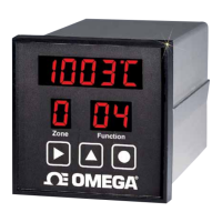
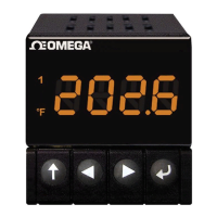
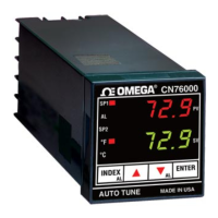
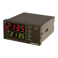
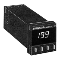
Identifies the components and displays on the front panel of the controller.
Explains the operation of the buttons on the controller for various functions.
Details the connectors and ports located on the back of the controller.
Describes the main display for monitoring temperature and setpoints.
Explains how the controller operates in PID control mode for each zone.
Details the RAMP and SOAK control mode where output turns off at profile end.
Describes RAMP and SOAK control mode maintaining last setpoint indefinitely.
Provides a brief overview of the organization of setup and operation functions.
Explains the password protection feature for safeguarding setup parameters.
Guides the user on navigating and selecting functions within the setup menu.
Details how to configure the controller's model, alarms, and other basic settings.
Covers setting individual zone setpoints, high alarms, and low alarms.
Explains how to adjust PID parameters like Proportional band, Reset, and Rate.
Covers setting the number of segments for profile control in each zone.
Details how to program setpoints, slopes, and times for ramp and soak profiles.
Procedure for setting the desired setpoint and zone for autotuning.
Instructions on how to initiate and execute the autotuning process.
Guidance on calibrating the controller for accurate measurements.
How to initiate a programmed temperature profile for one or all zones.
| Control Type | On/Off, PID |
|---|---|
| Display Type | Dual 4-digit LED |
| Power Supply | 100 to 240 VAC |
| Input Type | Thermocouple, RTD |
| Output Type | Relay, SSR |
| Control Algorithm | PID |
| Temperature Range | 0 to 400°C |