The REC-43 is a “stand-alone” universal receiver unit for 12 Volt applications. It has 4 outputs, which can be assigned to any of the transmitter’s
buttons. When the REC-43 receives a signal from the included transmitter, it activates the pre-assigned output. When activated the outputs supply
500mA (-) negative ground (500 milliamps = 0.5amp of ground). Each of the outputs may be congured as:
a) “TIMED PULSE” = When the output is activated, it will last for a preset period of time, from @ 1/5 of a second to @ 30 seconds.
b) “ON DEMAND” = When the output is activated, it will last for as long as the transmitter’s button is pressed.
c) “LATCH / UNLATCH” = When the output is activated, it will remain activated until an additional signal is received from the transmitter.
SEE THE INSTRUCTIONS ON THE OTHER SIDE OF THIS PAGE FOR CONFIGURING THE OUTPUTS
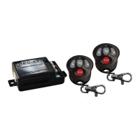
REC-43
Accessory Receiver Unit
Omega Research and Development
www.caralarm.com
4-pin 3-position DIP switch can congure each output
to operate in one of three ways- see text above
Variable adjustment for Timed Pulse output
Transmitter Programming Switch
© 2012 Omega Research and Development Technologies, Inc. | www.caralarm.com | 800.554.4053
ONE OR MORE U.S. PATENTS MAY APPLY TO THIS ITEM
Red wire: (+) 12 Volts Input, on the 4-pin plug supplies power to operate the REC-43.
Black wire: Negative Ground, must be connected to the negative side of the power source like a vehicle’s chassis.
The Outputs: are numbered as #1, #2, #3, and #4 in reference to their sequence within the transmitter programming procedure (see “Program-
ming Transmitters” and “Conguring Outputs”). Specic connection of these wires is contingent upon the application. When the REC-43 is used
to operate other controlling devices (remote engine starter, for example), connection is typically wire-to-wire directly to the device’s activation
wire. The other most common interface method is connecting the output wire to activate a relay to control the vehicle’s circuit (an example would
be locking or unlocking the doors). All 4 outputs have a 500mA capacity that should not be exceeded.
Note: The center pin on the 3-pin plug is (+) 12 Volts Output (500mA). It provides power to relay coils only of an optional door lock/unlock in-
terface.
Red wire = (+) 12 Volts Input
Black wire = (-) Chassis Ground Input
Blue wire = Output #3 (TRUNK)
Green wire = Output #4 (CH 3)
Green wire = Output #1 (LOCK)
center pin = (+) 12 Volts Output
Blue wire = Output #2 (UNLOCK)
Transmitter Functions Reference Guide
LOCK: Press and release the “LOCK” button.
THE DOORS WILL LOCK•
UNLOCK: Press and release the “UNLOCK” button.
THE DOORS WILL UNLOCK•
TRUNK RELEASE: Press and release the “TRUNK” button
THE TRUNK WILL OPEN •
(IF CONNECTED)
ACTIVATE 3RD CHANNEL: Press and release the “
...
”
button
THERE IS NO VISUAL OR AUDIBLE •
INDICATION. IF CONNECTED TO AN
OPTIONAL ACCESSORY, IT MAY
PROVIDE CONFIRMATION.
Antenna Wire
Programming Indicator Light
About The REC-43 Module Operation
Wiring Overview
REC-43T+ Keyless Entry System