If machining a trigger pattern into the front pulley then it is usually easiest to machine all of the teeth in,
mount the front pulley, and then remove the tooth pointing at the sensor at 90
o
BTDC.
There are two types of crank position sensor; MVR and Hall Effect. The Hall Effect type require ignition
switched power to make them work.
2 wire sensors must be MVR. Usually terminal 1 is the signal and terminal 2 the timing ground
3 wire sensors can be either MVR or Hall Effect. If MVR, then usually terminal 1 is the signal, terminal
2 the timing ground and terminal 3 has no connection. If Hall Effect, there is no way of measuring
externally to find which pin has which function; you must find out from the manufacturer.
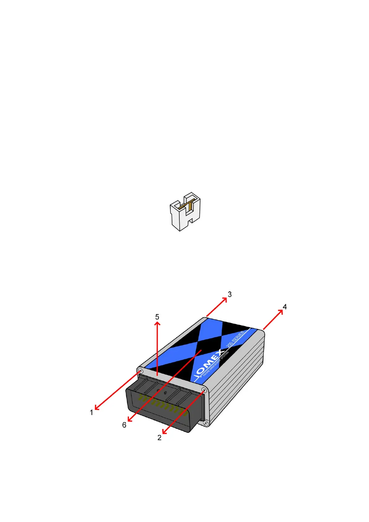
If the sensor is Hall Effect, a jumper (supplied with the ECU) must be put onto header pins on the ECU
board.
To fit this part you will need to part-disassemble the ECU to gain access to the board. As shown in the
diagram;
· remove screws (1, 2, 3 and 4)
· slide up the end plate (5)
· slide off the lid plate (6)
OMEM200 Installation Manual 2v10
6
Sensor
 Loading...