The ECU needs to know engine speed and position in order to supply the correct fuelling and ignition
timing. This is often achieved using the standard sensors, but can involve putting new sensors on the
engine. Engine speed is measured using a pattern of teeth on a crank wheel or flywheel (known as a
trigger wheel). The 200 ECU supports the following patterns;
Ford 36-1 Rover 18-1, 18-1 (distributor ignition only)
Bosch 60-2 Toyota 36-2
Rover K (late) Honda 12+1
If you have any doubt as to whether the trigger pattern on your engine is supported by the 200 ECU,
then remove the sensor, count the pattern of teeth, and contact Omex.
Many older engines do not have a trigger wheel. In this case an external wheel must be fitted. 36-1 is
our preferred pattern. There is a minimum diameter for these wheels dependent on the sensor used,
the trigger pattern, and the engine operating speeds. Typically the larger the trigger wheel diameter the
better. The wheel needs to be mounted on the front pulley. It may also be possible to machine this
pattern into the front pulley wheel, remembering that the pattern must be in a ferrous material for the
sensor to work and if the crank pulley has a damper inbuilt you must mount the trigger wheel onto the
crank side of this damper. Omex can supply general purpose trigger wheels in diameters of 100mm and
140mm.
If installing a trigger wheel of missing tooth type,
Ÿ Accurately mark TDC.
Ÿ Mount your crank position sensor (CPS) anywhere around the perimeter of the trigger wheel
pointing towards the centre of the wheel such that the sensor can touch the pulley (it will be
spaced out so that it does not touch later). The mount should be strong enough that you can
lean on it and it not move.
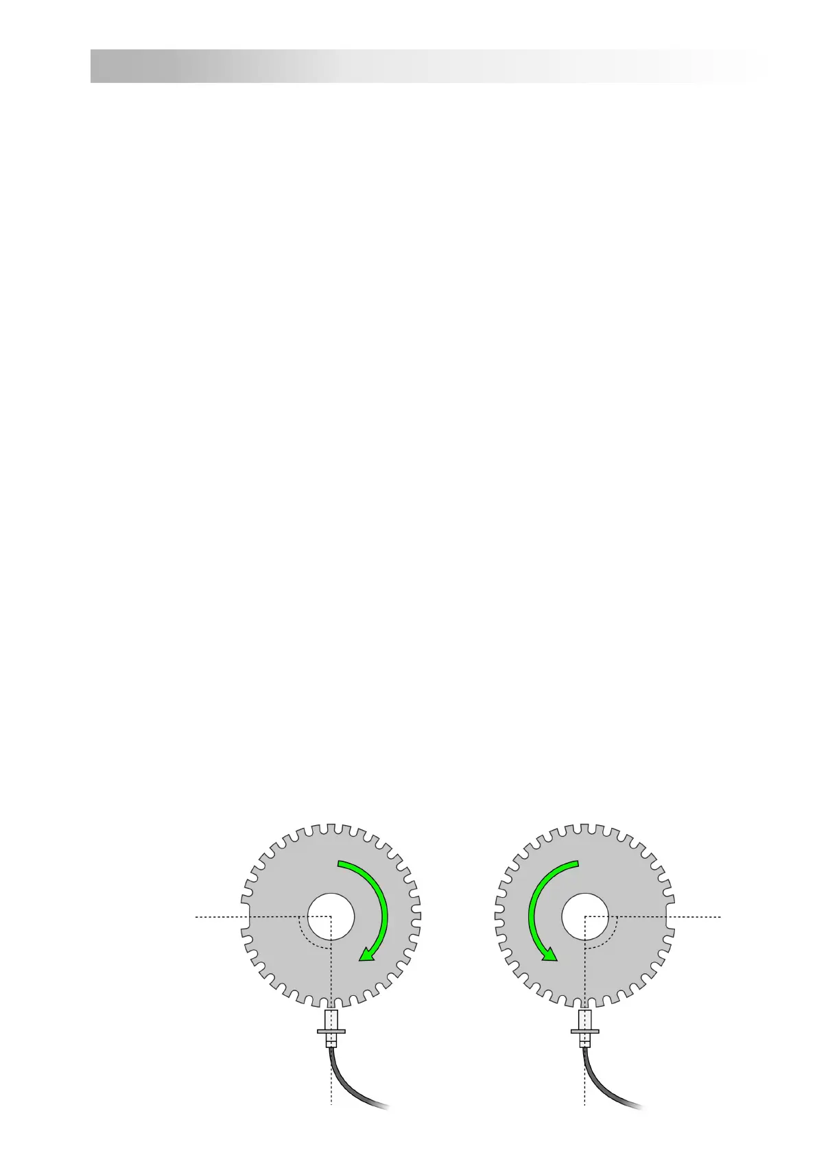
Ÿ Mount the trigger wheel so that the missing tooth is approximately 90 degrees after the crank
sensor. (the exact angle can be adjusted in software but for first start of the engine it helps if
you are within 10 degrees of this position). If the crank pulley has a damper inbuilt you must
mount the trigger wheel onto the crank side of this damper.
Ÿ Run the crank pulley / trigger wheel assembly in a lathe to ensure that the trigger wheel is
exactly central on the pulley.
Ÿ Refit the pulley / trigger wheel assembly and adjust the sensor-to-wheel gap to 0.3mm-
0.5mm by spacing out the sensor with shims.
Ÿ Rotate the pulley and ensure that the gap does not alter by more than 0.2mm.
Trigger Wheel
OMEM200 Installation Manual 2v10
5
Anti-clockwise rotating engine
at cylinder 1 TDC
90°90°
Clockwise rotating engine
at cylinder 1 TDC
2 Standard Functions
2.1 Crank Position Sensor (CPS)
 Loading...