OMNI 4000/7000 Operations and Maintenance Guide – Rev F
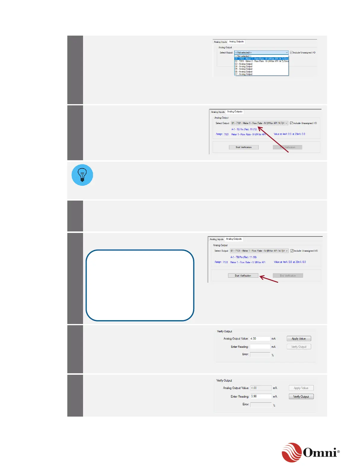
a. Click on the Analog Output tab.
b. Select an analog output channel to
verify from the Select Output
drop-down box.
To include output channels in the
drop-down list that have not been assigned
in the configuration, check the Include
Unassigned I/O box.
If the channel has been assigned in the
configuration, confirm that the Modbus
Register Assignment, Remark and Values
at 4 mA and 20 mA are displayed in
blue text.
If the Remark field is not filled in during the Analog output channel configuration, then
the Modbus register’s database description, the hardware module and the Terminal
Block pin numbers are still displayed in blue text after a selection is made. If the
output channel is unassigned, only the hardware module and Terminal Block pin
numbers are still displayed in blue text.
Connect an ammeter to the Terminal
Block output pins in series between the
flow computer and the external 4‒20 mA
device.
When ready to begin the verification
process, click Start Verification.
a. In the Verify Output group, enter an
Analog Output Value.
b. Click Apply Value.
The flow computer will output the value
using the current calibration constants.
a. Enter the value displayed on the
ammeter in the Enter Reading field.
b. Click Verify Output.
This action records the following
information in the Measurement
Audit Trail Log:
• Time, date and output index
• Output # ‘n’ calibration start
(n = output channel number)
• User name, user ID and port
hosting the calibration
 Loading...