EasyManua.ls Logo

Omnimount PLAY20x

Omnimount PLAY20x
24 pages
To Next Page IconTo Next Page
Loading...
PN:888-45-232-W-01
INSTRUCTION MANUAL
MANUAL DE INSTRUCCIONES
MANUEL D’INSTRUCTIONS
BENUTZERHANDBUCH
INSTRUCTIEHANDLEIDING
MANUALE DI ISTRUZIONI

NÁVOD K OBSLUZE
KEZELÉSI KÉZIKÖNYV

MANUAL DE INSTRUÇÕES
BRUGERVEJLEDNING
ASENNUSOPAS
MONTERINGSANVISNING
MANUAL CU
NAVODILA


BRUKSANVISNING
󴸤󲠾󲑻󱎼
󱘆󲒡󴳜󲠾󲤨
PLAY20x
INTERACTIVE TV MOUNT
VERSION C
Reduce.Reuse.Recycle
OM# OM1100573
PN# PLAY20x = L20-OM1100573-CON-022112vC
Max screen size: 32”
Max weight 20 lbs – 9.07 kg
CAUTION: DO NOT EXCEED
MAXIMUM LISTED WEIGHT
CAPACITY. SERIOUS INJURY
OR PROPERTY DAMAGE MAY
OCCUR!
Question and Answer IconNeed help?

Do you have a question about the Omnimount PLAY20x and is the answer not in the manual?

Omnimount PLAY20x Specifications

General IconGeneral
Mounting typeWall
Maximum VESA mount200 x 100 mm
Minimum VESA mount75 x 75 mm
Maximum screen size32 \
Minimum screen size19 \
Maximum weight capacity9.1 kg
Pan range0 - 180 °
Turn angle180 °
Tilt angle range-70 - 5 °
Distance to the wall (max)650 mm
Product colorAluminum

Summary

DISCLAIMER AND WARNING INFORMATION

General Warning: Read and Follow Instructions

Failure to follow instructions can result in serious injury, damage, or voided warranty.

WEIGHT CAPACITY AND SCREEN SIZE

Maximum Weight Capacity Warning

Exceeding max weight can cause product failure, injury, or property damage.

VESA PATTERN CONFIGURATIONS

VESA Pattern A (75 x75 mm, 100 x100 mm)

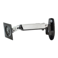
Configuration for 75x75mm and 100x100mm VESA mounting patterns.

VESA Pattern B (100 x200 mm)

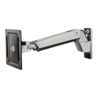
Configuration for 100x200mm VESA mounting patterns.

VESA Pattern C (200 x200 mm)

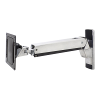
Configuration for 200x200mm VESA mounting patterns.

VESA Pattern D (200 x100 mm)

Configuration for 200x100mm VESA mounting patterns.

STEP 1 A: ATTACH TV TO MOUNT

STEP 1 B-C-D: INSTALL ADAPTERS

STEP 2: WOOD STUD INSTALLATION

STEP 2: SOLID CONCRETE INSTALLATION

STEP 3: HANG WITH MONITOR ATTACHED

STEP 3 B: OPTIONAL EXTENSION ARM INSTALLATION

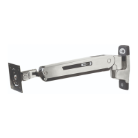
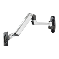
Instructions for installing an optional extension arm.

STEP 4: DO NOT OVER-TIGHTEN

STEP 4 B: OPTIONAL EXTENSION ARM INSTALLATION

Instructions for optional extension arm, avoiding over-tightening.

STEP 5: ATTACH COVERS

ATTENTION: INTERACTIVE ADJUSTMENT WARNING

STEP 6: INTERACTIVE ADJUSTMENT

STEP 7: INTERACTIVE ADJUSTMENT

STEP 8: INTERACTIVE ADJUSTMENT

STEP 9: EXTENSION CABLE MANAGEMENT

WARRANTY INFORMATION

Notice to Customer Outside United States

How to obtain warranty service for international customers.

Related product manuals