00041723.DOC, Version 1.1
17/19
5. INSTALLATION
5.1 Rack installation
Install the unit on a plane surface or in your rack. For 19" (483 mm) rack installation, 1 unit is required. When
mounting the unit into the rack, please make sure that there is enough space around the unit so that the
heated air can be passed on. Steady overheating will damage your unit. You can fix the unit with four screws
M6 in the rack.
5.2 Audio connections
Switch off the mixer prior to connecting any units or to changing any existing connections.
1 Connect stereo units with line level (e.g. CD players) to the RCA inputs SOURCE 1-3 (white jack = left;
red jack = right).
2 It is possible to connect both microphones (balanced or unbalanced) and mono units with line level to the
inputs of the mono channels MIC 1-3. For phantom powered microphones you can switch on a 12 V
phantom power via the dip switches (see chapter 6.1).
Caution! If the phantom power is switched on, no unbalanced microphones or units with line level must be
connected to the corresponding inputs. Otherwise, these microphones and units may be
damaged.
3 An external effects unit can be inserted via the jacks SEND and RETURN. Connect the mono output (6.3
mm jack) SEND to the input and the stereo input LEFT/RIGHT RETURN to the output of your external
effects unit.
4 A PA amplifier for speakers or a subsequent unit with line level can be connected to the 6.3 mm jacks
LEFT OUT and RIGHT OUT.
5 For sound recordings, connect the recording unit to the RCA output REC OUT. The recording level is
independent of the position of the master control.
5.3 Connection with the mains
Connect the device to the mains with the supplied power supply cable.
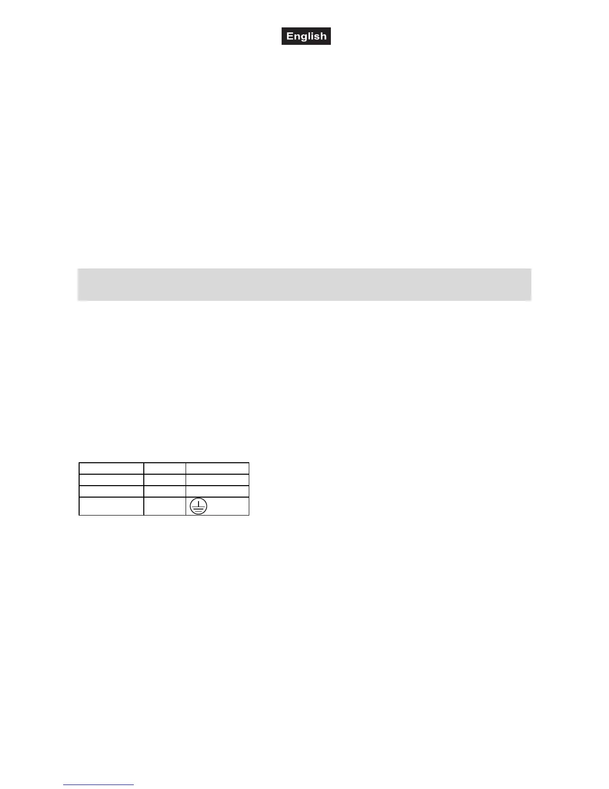
The occupation of the connection cables is as follows:
Cable Pin International
Brown Live L
Blue Neutral N
Yellow/Green Earth
The earth has to be connected!
If the device will be directly connected with the local power supply network, a disconnection switch with a
minimum opening of 3 mm at every pole has to be included in the permanent electrical installation.
The device must only be connected with an electric installation carried out in compliance with the IEC-
standards. The electric installation must be equipped with a Residual Current Device (RCD) with a maximum
fault current of 30 mA.