00036961.DOC, Version 1.0
14/18
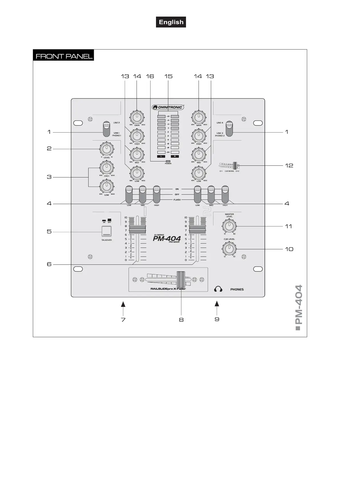
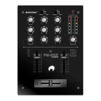
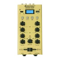
4.2 Operating elements and connections
1 Input selector switches
For selecting the input source for channel 1 and channel
2.
2 Level control for the DJ microphone.
3 Tone controls
2-way equalizers for the DJ microphone: HIGH and LOW.
4 Kill switch
For suppressing certain frequency ranges. Upper position
“ON“: the respective frequency band is attenuated to a
large extent (LOW = bass range, MID = midrange, HIGH
= high range). Middle position “OFF“: the Kill function is
deactivated. Lower position “FLASH“: as long as the
switch is held, the respective frequency band is
attenuated to a large extent (LOW = bass range, MID =
midrange, HIGH = high range).
5 Talkover
Selector switch (with indicating LED) for an automatic
level attenuation (16 dB) of both channels in case o
microphone announcements with a DJ microphone.
6 Faders
Level controls for channel 1 and channel 2.
7 DJ microphone
6.3 mm jack (bal.) at the front of the unit for connecting a
DJ microphone.
8 Crossfader
For crossfading between channel 1 and channel 2. In
mid-position, both channels can be heard.
9 Headphones input
6.3 mm jack PHONES at the front of the unit fo
connecting stereo headphones.