00036961.DOC, Version 1.0
16/18
5. INSTALLATION
The unit can be used as a table top unit as well as be installed into a console. Switch off the mixer prior to
connecting any units or to changing any existing connections.
1. Connect the stereo audio sources to the corresponding RCA jacks of channel 1 and channel 2 (white jack
= LEFT; red jack = RIGHT):
- Connect units with line level output (e. g. CD/MP3 player) to the jacks LINE
- Connect turntables with magnetic system to the jacks PHONO. Connect the ground lead of the turntable to
the clamping screw GND.
2. Connect a DJ microphone to the 6.3 mm jack at the front of the unit.
3. Connect the amplifier to the unbalanced RCA master output.
4. For sound recordings, connect the recording unit to the output REC. The recording level is independent of
the position of the master control.
5. The input channels can be monitored via stereo headphones ahead of the faders. Connect the
headphones to the jack PHONES.
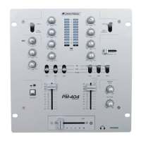
6. Connect the power supply unit to the AC IN jack of the PM-404 and the mains plug to a mains socket.
Use the unit only with the supplied OMINTRONIC power unit. Always disconnect the mains connector when
you wish to change connections, move the unit to a different place or if it is not used for a longer period.
6. OPERATION
Prior to switching on, turn the master control to position “0“ to avoid damage to the hearing by a volume
which is too high when switching on. Then switch on the unit with the power on/off switch. The power
indicator on the front panel lights up. Finally switch on the connected units. After operation, switch off the unit
with the power on/off switch.
6.1 Basic adjustment of the input channels
First set all gain controls, equalizer controls, and the crossfader to mid-position and the TALKOVER switch to
OFF.
Level control of a channel:
1. Use the input selector switch to select the input to which the audio source is connected.
2. The master control determines the total level of all connected audio sources. Set the control to approx. 2/3
of its maximum, e.g. to position “7”.
3. Feed an audio signal (test signal or music piece) to the channel. Switch off the units which are to play on
the other channel or set them to pause.
4. Via the output meter, control the level of the respective channel with the fader. An optimum level control is
obtained if level values in the 0 dB range are shown at average volume. If the red LEDs of the output meter
light up, there is an overload of the channel.
5. Then adjust the desired sound with the tone controls of the channel. By adjusting the three tone controls,
the high frequencies (control HIGH), the midrange frequencies (control MID), and the low frequencies
(control LOW) can be boosted (12 dB max.) or substantially attenuated (36 dB max.) With the controls in
mid-position, the frequency response is not affected.
Note: Sound adjustments affect the level. Therefore, after adjusting the sound, check the channel level with
the output meter and readjust it, if required.
6. Repeat the steps for level and sound adjustments for the other connected input channel as described
above.