If input is performed simultaneously with the OPE terminal (35: Forced operator), the forced operator
is given priority.
The frequency reference for the forced terminal block function is the frequency reference based on the
input terminals [AI1] + [AI1](AII).
The RUN command for the forced terminal block function is the FW terminal and the RV terminal allo-
cated to the input terminal. If the FW terminal and RV terminal are not allocated to the input terminal, it
becomes impossible to perform operation.
The forced terminal block function is given priority in the case of frequency reference than the multi-
step speed reference.
When the start check function is set to enabled, the start check function is executed when the F-TM
terminal (162: Forced terminal block) is turned ON. (For details on the start check function, refer to
7-7-7 ST
OP Key Priority/Start Check Function on page 7-80.)
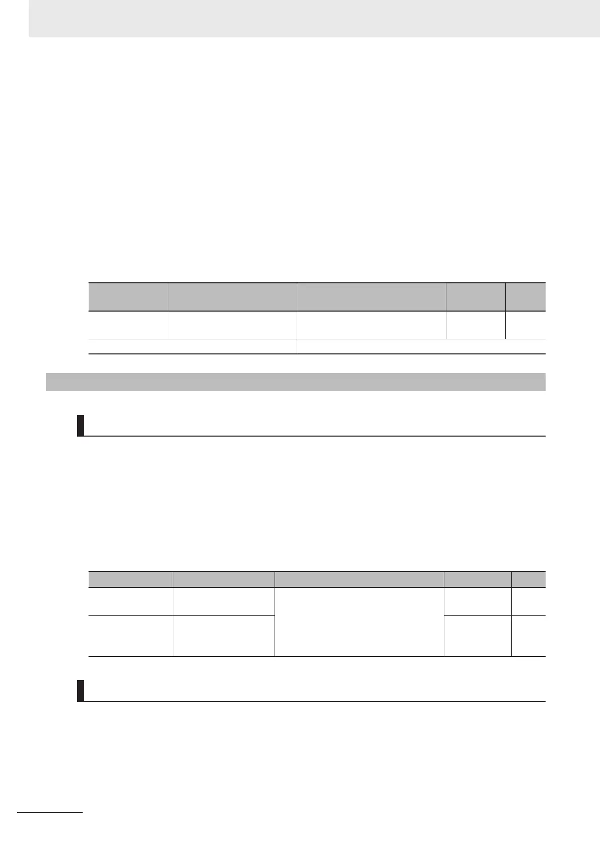
Parameter No. Function name Data
Default da-
ta
Unit
E01 to E05, E98,
E99
Input Terminal [DI1] to [DI7]
Function Selection
162: F-TM (Forced terminal block) - -
Related function F01, C30, F02, E102
7-7-4
Initial Screen Selection
LED Monitor (Item Selection)
This function makes it possible to select the monitor information of the operation status displayed on
the Operator LED.
If speed monitor is selected at Operator Display Selection during Run (E43), the display is in the
speed form selected at Operator Display Speed Monitor Item Selection (E48).
If the Operator is not operated for five minutes, the display automatically changes to the initial screen
selected at Operator Display Selection during Run (E43).
For details on Operator Display Selection during Run (E43) and Operator Display Speed Monitor Item
Selection (E48), refer to 3-1-2 Key Operation Method on page
3-3.
Parameter No. Function name Data Default data Unit
E43
Operator Display Se-
lection during Run
Refer to 3-1-2 Key Operation Method
on page 3-3.
0 -
E48
Operator Display
Speed Monitor Item
Selection
0 -
LED Monitor (Display when Stopped)
Select the monitor information to be displayed on the Operator when the inverter is stopped. The set
frequency is displayed in the case of Operator Display when Stopped Selection (E44) = 0 and the out-
put frequency is displayed in the case of Operator Display when Stopped Selection (E44) = 1. The dis-
play format is that selected at Operator Display Speed Monitor Item Selection (E48).
7 Other Functions
7-76
M1 Series Standard Type User's Manual (I669)
 Loading...


