Parameter No. Function name Data Default data Unit
E20, E21, E27
Output Terminal [DO1]
Function Selection,
Output Terminal [DO2]
Function Selection,
Output Terminal [ROA,
ROB] Function Selec-
tion
77: U-EDC (Low DC link bus voltage
detection)
- -
Main Circuit DC Voltage L
ow-voltage Detection Level (E76)
Main Circuit
DC Voltage
“U-EDC”
7-8-25
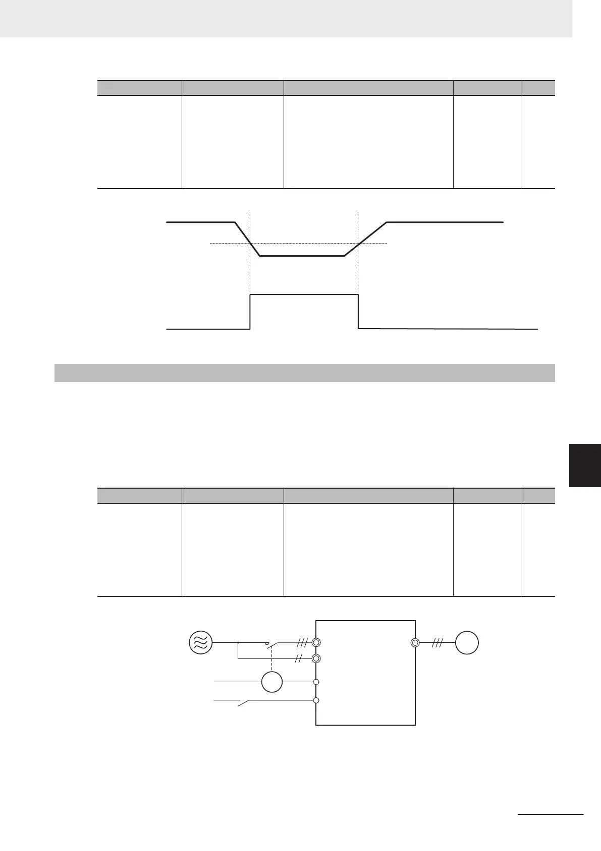
AX Terminal Function (AX)
This function is used to control the electromagnetic contactor at the inverter input side in association
with the RUN command. It turns ON when the RUN command is input. When the stop command is
input, this function turns OFF after the inverter undergoes a deceleration stop. This function turns OFF
momentarily when the free run command is input and an alarm is generated.
“AX” can be selected at a capacity of 18.5kW or more of auxiliary power supply.
Connect the power supply directly between R0 and T0.
Parameter No. Function name Data Default data Unit
E20, E21, E27
Output Terminal [DO1]
Function Selection,
Output Terminal [DO2]
Function Selection,
Output Terminal [ROA,
ROB] Function Selec-
tion
15: Switch MC on the input power lines
(for inverter input-side electromagnetic
contactor)
- -
L1/R to L3/T
R0, T0
DO1 (“AX”)
FW
U, V, W
M
Power supply
“FW”
Motor
3G3M1
MC
MC
7 Other Functions
7-107
M1 Series Standard Type User's Manual (I669)
7-8 Functions Related to Protection, Warning and Various Output Signals
7
7-8-25 AX Terminal Function (AX)
 Loading...


