LED No. LED4 LED3 LED2 LED1
Dis-
play
exam-
ple
Binary 0 0 1 0 0 0 0 0 0 0 1 0 0 0 0 1
Hexa-
decimal
Hexa-
decimal
LED
monitor
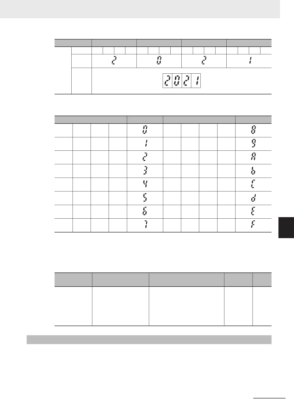
The input of light alarm selection must be made by converting a binary 4 bits unit to hexadecimal.
The conversion table is shown below.
Binary Hexadecimal Binary Hexadecimal
0 0 0 0 1 0 0 0
0 0 0 1 1 0 0 1
0 0 1 0 1 0 1 0
0 0 1 1 1 0 1 1
0 1 0 0 1 1 0 0
0 1 0 1 1 1 0 1
0 1 1 0 1 1 1 0
0 1 1 1 1 1 1 1
Light Alarm L-ALM Signal
If “98: L-ALM (Minor alarm)” is allocated to Output Terminal [DO1] Function Selection (E20), Output
T
erminal [DO2] Function Selection (E21) and Output Terminal [ROA, ROB] Function Selection
(E27), the minor alarm “L-ALM” signal is output when the cause of a minor alarm occurs.
Parameter No. Function name Data
Default da-
ta
Unit
E20, E21, E27
Output Terminal [DO1]
Function Selection, Output
Terminal [DO2] Function
Selection, Output Terminal
[ROA, ROB] Function Se-
lection
98: L-ALM (Minor alarm) - -
7-8-27
Input Phase Loss Protection / Output Phase Loss Protection
By setting Input Phase Loss Protection Function Selection (H411) and Output Phase Loss Protection
Function Selection (H412), it is possible to set whether to continue with the operation or trip the inver-
ter when an input loss or output loss is detected.
7 Other Functions
7-111
M1 Series Standard Type User's Manual (I669)
7-8 Functions Related to Protection, Warning and Various Output Signals
7
7-8-27 Input Phase Loss Protection / Output Phase Loss Protection
 Loading...


