8-7
Modbus Mapping Function
This Modbus mapping function can change up to 10 register addresses.
For example, when designing replacements, you can match the inverter-side register addresses with-
out changing the communications program.
It is also possible to set the data type, scale, and endian (byte order) of communication data according
to your application.
8-7-1
Operation of Modbus Mapping Function
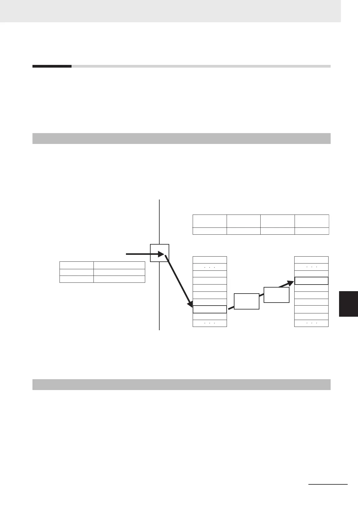
The Modbus mapping function can set up to 10 register addresses.
This function processes the command, which is sent to the external register address specified from
the external communications, for data in the address set in the internal register.
Even if the data are different between the external and internal registers, it is possible to adjust this
using data types and scaling settings.
……………………………
……………………………
……………………………
……………………………
Command from
external communications
Address
Command
Data
1005h
0001h
External register
External register
(Connection process)
Internal register
Data type
conversion
×
Scale
……………………………
……………………………
……………………………
……………………………
……………………………
Inside inverter
P201 P211 P221 P301
1001h2.00001: Signed1005h
Data type Scale
Internal register
10 hex (Write to register)
Communications
terminal
Modbus mapping function settings (P200 = 01: Enabled)
1000h
1000h
1001h
1001h
1002h
1002h
1003h
1003h
1004h
1004h
1005h
1005h
1006h
*1
1006h
×
*1. The internal register (Modbus register inside the inverter) that overlaps with the external register setting is dis-
abled.
To use that internal register, set an external register not to overlap or set a dif
ferent Modbus mapping function
to access from a different register address.
8-7-2
Modbus Mapping Function Settings
To use the Modbus mapping function, set the Modbus Mapping Function Selection (H355) to “01:
Modbus mapping function enabled” and set each parameter.
• Each number of 1 to 10 in Modbus Mapping External Register
, Modbus Mapping External Register
Type, Modbus Mapping Scaling, and Modbus Mapping Internal Register corresponds to one set of
Modbus mapping function settings, respectively.
• In the Modbus Mapping 1 External Register to Modbus Mapping 10 External Register (H356 to
H365), set the register address to receive commands from external communications.
• In the Modbus Mapping 1 External Register Sign to Modbus Mapping 10 External Register Sign
(H366 to H375), set the data type used for the external register on the external communications
8 Communications Functions
8-23
M1 Series Standard Type User's Manual (I669)
8-7 Modbus Mapping Function
8
8-7-1 Operation of Modbus Mapping Function
 Loading...


