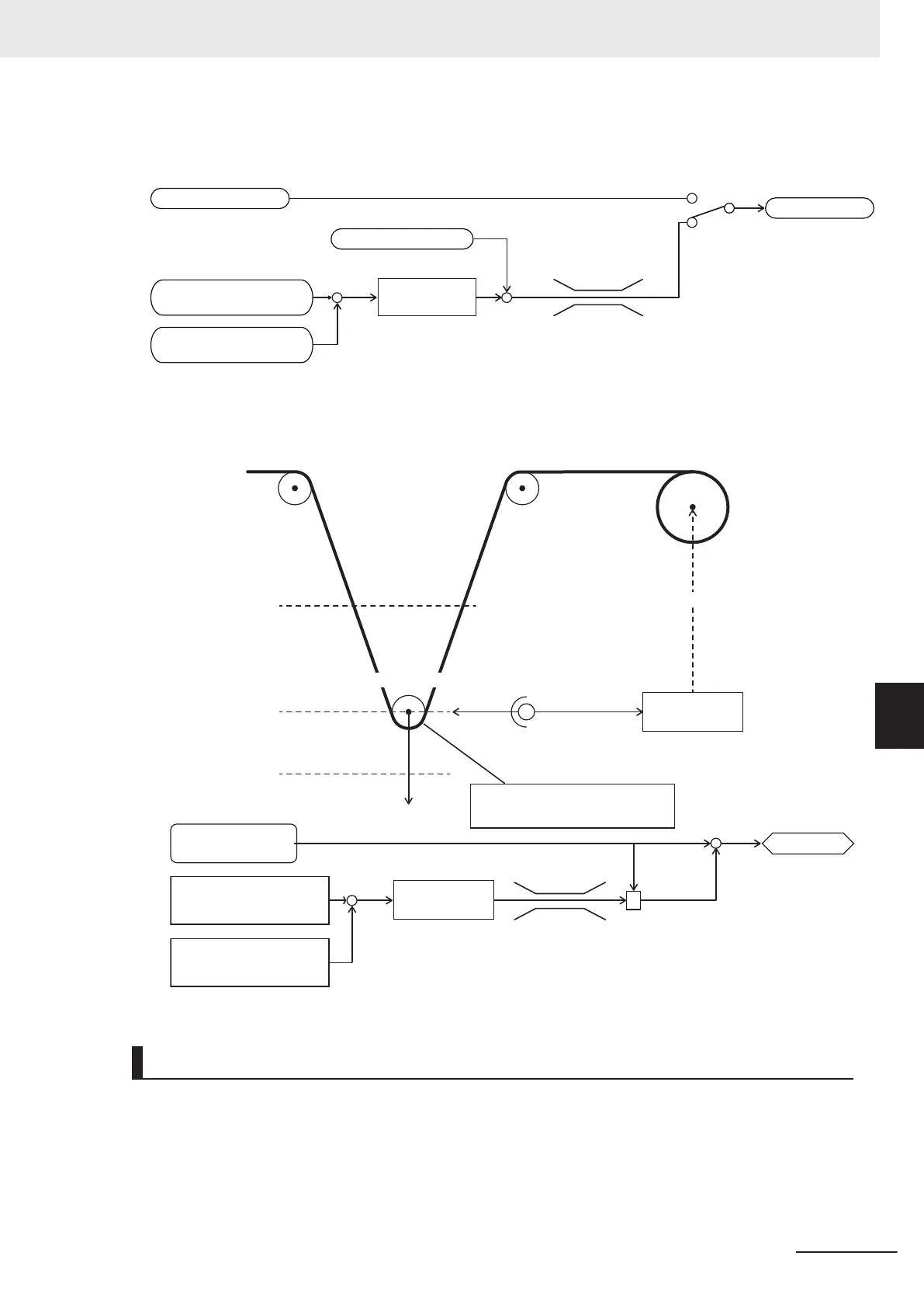
Schematic block diagram of PID process control
When PID Control Function Selection (J01) = “1,” “2,” “4,” “5”
+
+
+
-
Manual speed command
Feedforward
PID controller
Frequency reference
PID Control PID
Output Upper Limit (J18)
PID Control PID
Output Lower Limit (J19)
PID Control PID
Command Selection (J02)
PID Control
Feedback Selection (E119)
Schematic block diagram of PID dancer control
When PID Control Function Selection (J01) = “3”
+
-
x
+/-
+
PID Control PID
Command Selection (J02)
(Dancer position set point)
PID Control PID
Command Selection (J02)
(Dancer position feedback)
PID calculation
Frequency reference
Speed command
(Main setting)
PID Control PID
Output Upper Limit (J18)
PID Control PID
Output Lower Limit (J19)
Fixed roll Fixed roll
Upper
limit position
Reference position
Lower limit position
Dancer roll
F
Adjust the line speed with reference
to the position of the dancer roll
Inverter
Rotation speed control
Potentiometer, etc.
Position information
ex. 0 to 10 V
Wind-up
machine
PID Operation
1. PID Control P Proportional Gain (J03)
In this operation, the operation amount is proportional to the deviation (difference between the tar-
get value and the current value).
7 Other Functions
7-127
M1 Series Standard Type User's Manual (I669)
7-9 Other Operation Functions
7
7-9-13 PID Function
 Loading...

