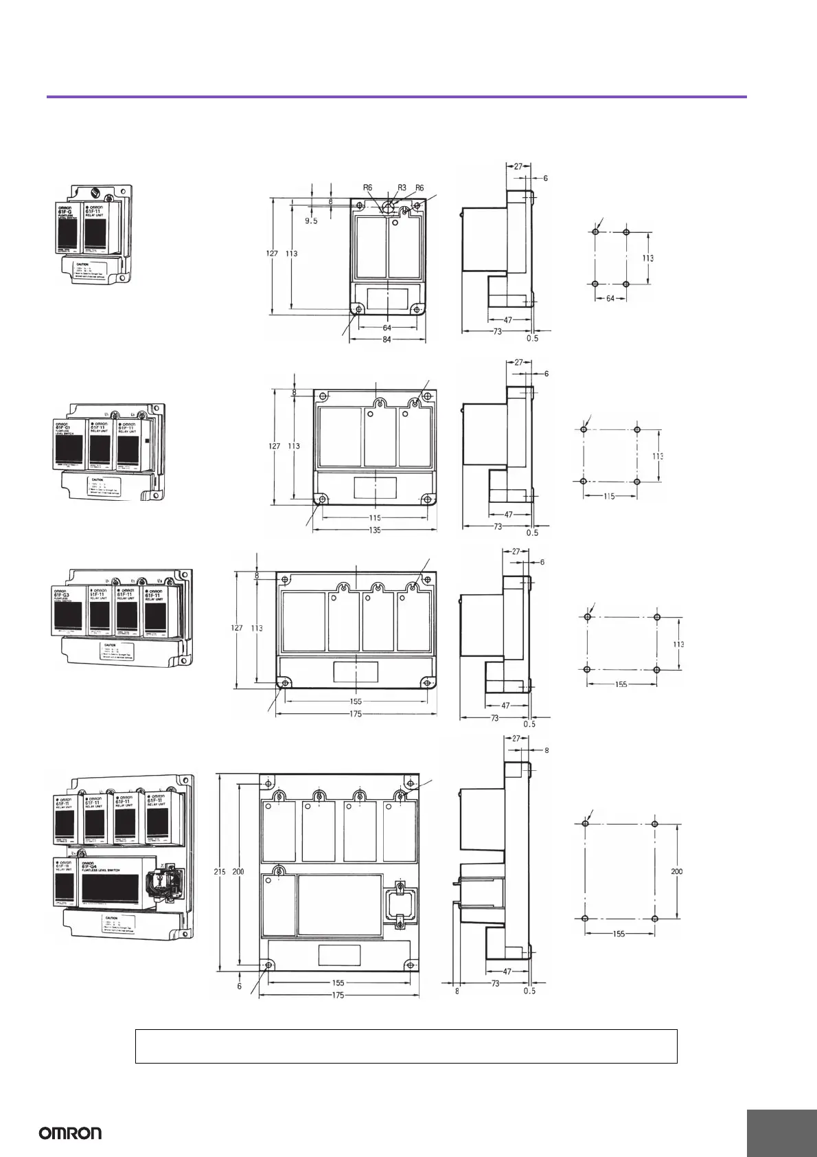
EasyManuals Logo

Omron 61F-G User Manual

Omron 61F-G
15 pages
To Next Page IconTo Next Page
To Previous Page IconTo Previous Page
Page #14 background imageLoading...
Page #14 background image
61F-G@
14
Dimensions
Note: All units are in millimeters unless otherwise indicated.
Standard Models
61F-G
Mounting Holes
M3 screw
Four, 6-dia holes
Four, 6-dia mounting holes
61F-G1
61F-G2
61F-I
Mounting Holes
Four, 6-dia holes
Four, 6-dia mounting holes
M3 screw
61F-G3
Mounting Holes
M3 screw
Four, 6-dia holes
Four, 6-dia mounting holes
61F-G4
Mounting Holes
Four, 6-dia holes
M3 screw
Four, 6-dia mounting holes
In the interest of product improvement, specifications are subject to change without notice.
ALL DIMENSIONS SHOWN ARE IN MILLIMETERS.
To convert millimeters into inches, multiply by 0.03937. To convert grams into ounces, multiply by 0.03527.

Questions and Answers:

Question and Answer IconNeed help?

Do you have a question about the Omron 61F-G and is the answer not in the manual?

Omron 61F-G Specifications

General IconGeneral
Operating Temperature-10 to 55°C
Contact Rating5A at 250 VAC
Electrode Voltage8 VAC
Model61F-G
Rated Current5A
Electrical Life100, 000 operations min.
Operating Temperature Range-10 to 55°C
Operating Humidity45% to 85% RH
OutputSPDT relay
Control MethodElectrode
Electrode CurrentApprox. 1 mA
MountingDIN rail
Rated Voltage100 to 240 VAC

Related product manuals