61F-G@
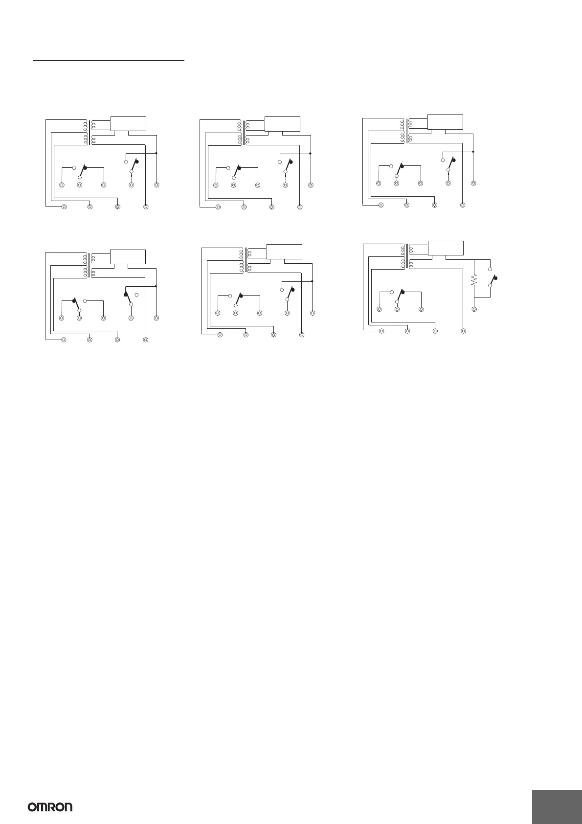
Internal Circuit Diagrams
The schematic diagrams shown below typify the internal connections of the various 61F models. The designations Ta, Tb, and Tc (sometimes
referred to collectively as “U”) may occur more than once in a product, however, the “a” terminal is always an NO contact, a “b” terminal is an NC
contact, and the “c” terminal is the common terminal.
61F-G
61F-GT 61F-GL
61F-GH
(See note.)
61F-GD 61F-GR
24 V
8 V
0 V
200, 220
or 240 V
100, 110
or 120 V
S
0 S1 S2 E3
Ta Tc Tb E1E2
U
U
U
61F-11
Relay Unit
24 V
8 V
0 V
200, 220
or 240 V
100, 110
or 120 V
S
0 S1 S2 E3
Ta Tc Tb E1E2
U
U
U
61F-11T
Relay Unit
24 V
8 V
0 V
200, 220
or 240 V
100, 110
or 120 V
S
0 S1 S2 E3
Ta Tc Tb E1E2
U
U
U
61F-11L
Relay Unit
24 V
24 V
0 V
200, 220
or 240 V
100, 110
or 120 V
S
0 S1 S2 E3
Ta Tc Tb E1E2
U
U
U
61F-11H
Relay Unit
24 V
8 V
0 V
200, 220
or 240 V
100, 110
or 120 V
S
0 S1 S2 E3
Ta Tc Tb E1E2
U
U
U
61F-11D
Relay Unit
24 V
8 V
0 V
200, 220
or 240 V
100, 110
or 120 V
S
0 S1 S2 E3
Ta Tc Tb E1
U
U
U
61F-11R
Relay Unit

 Loading...


