61F-G@
3
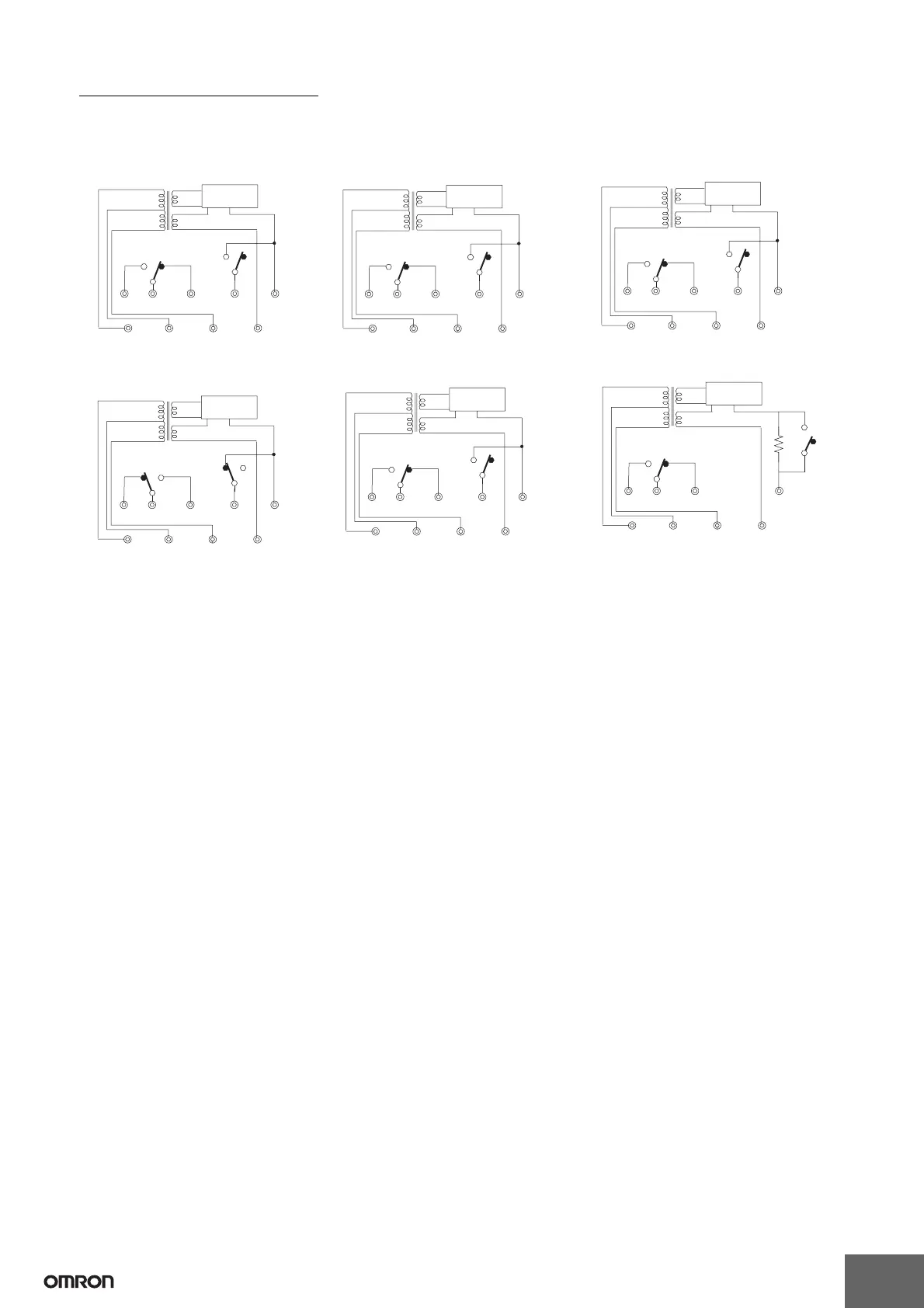
Internal Circuit Diagrams
The schematic diagrams shown below typify the internal connections of the various 61F models. The designations Ta, Tb, and Tc (sometimes re-
ferred to collectively as “U”) may occur more than once in a product, however, the “a” terminal is always an NO contact, a “b” terminal is an NC
contact, and the “c” terminal is the common terminal.
61F-G
61F-GT 61F-GL
61F-GH
(See note.)
61F-GD 61F-GR
24 V
8 V
0 V
200, 220
or 240 V
100, 110
or 120 V
S
0
S
1
S
2
E
3
Ta Tc Tb E
1
E
2
U
U
U
61F-11
Relay Unit
24 V
8 V
0 V
200, 220
or 240 V
100, 110
or 120 V
S
0
S
1
S
2
E
3
Ta Tc Tb E
1
E
2
U
U
U
61F-11T
Relay Unit
24 V
8 V
0 V
200, 220
or 240 V
100, 110
or 120 V
S
0
S
1
S
2
E
3
Ta Tc Tb E
1
E
2
U
U
U
61F-11L
Relay Unit
24 V
24 V
0 V
200, 220
or 240 V
100, 110
or 120 V
S
0
S
1
S
2
E
3
Ta Tc Tb E
1
E
2
U
U
U
61F-11H
Relay Unit
24 V
8 V
0 V
200, 220
or 240 V
100, 110
or 120 V
S
0
S
1
S
2
E
3
Ta Tc Tb E
1
E
2
U
U
U
61F-11D
Relay Unit
24 V
8 V
0 V
200, 220
or 240 V
100, 110
or 120 V
S
0
S
1
S
2
E
3
Ta Tc Tb E
1
U
U
U
61F-11R
Relay Unit
 Loading...