9
A22LK
Operating Environment
• The Switch is intended for indoor use only.
• Do not use the Switch outdoor, or the Switch will malfunction.
• Do not use the Switch in the atmosphere of hazardous gases (H
2S,
SO
2, NH3, HNO3, CI2, etc.) or high temperature and humidity, or it
will cause the imperfect closing of the contacts or the breakage
thereof stemming from corrosion.
• Do not use the Switch under any of the conditions mentioned
below.
• Frequent temperature range.
• High humidity or dew condensation may be generated.
• Where the Switch is subject to severe vibration.
• Where the metal dust, oil, or chemical is sprayed inside the door.
• Where thinner is applied.
Switch unit mounting
• Operation unit can be adjusted to any of the four directions.
• Do not remove the switch unit while energizing. Otherwise the
machine might mis-operate.
Storage
• Do not store the Switch where corrosive gases (e.g., H2S, SO2,
NH
3, HNO3, or Cl2) or dust is present, or in locations subject to high
temperature or high humidity.
Mounting
• Loose screws may result in malfunction.
Be sure to tighten each screw of the Switch properly.
• Do not tighten the mounting ring more than necessary using tools
such as pointed-nose pliers. Doing so will damage the mounting
ring. The tightening torque is 0.98 to 1.96 N·m.
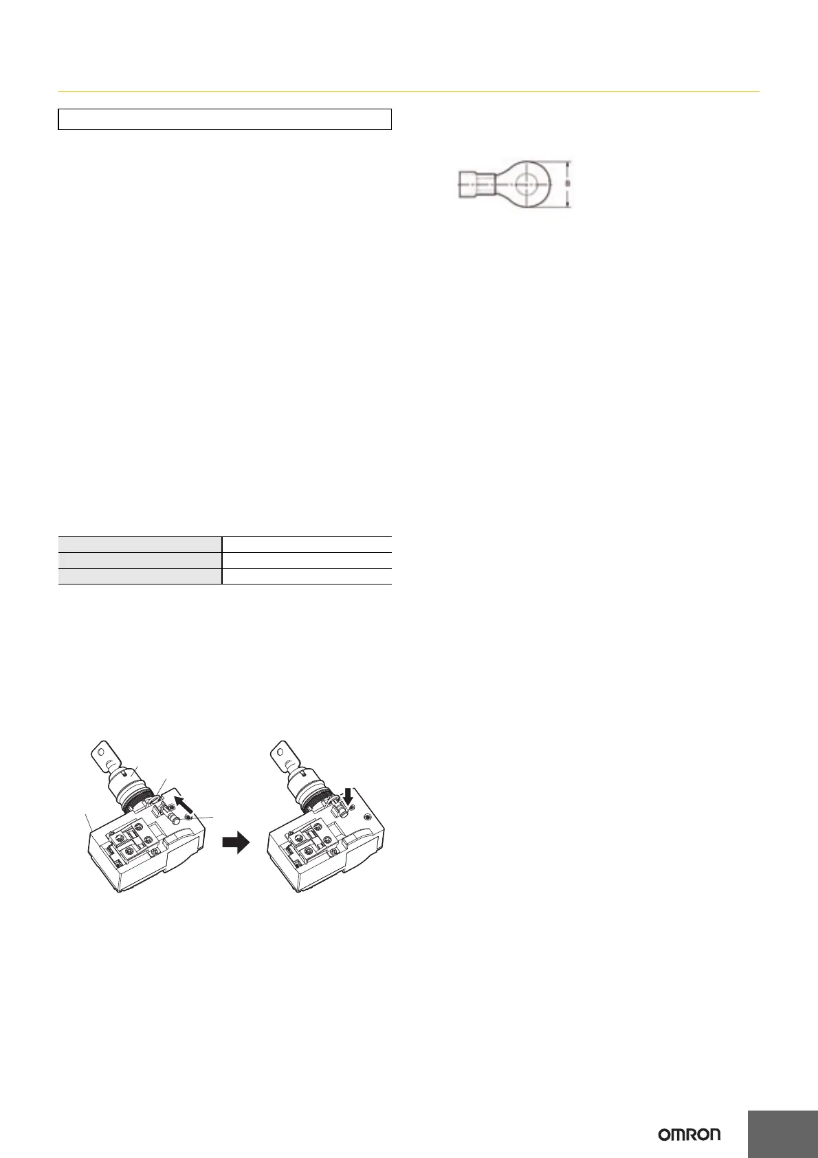
Lock pin
• Mount the lock pin to prevent the operation unit from coming off the
switch unit.
• Mounting the lock pin
(1) Confirm that the lever is on the “LOCK” position and then insert
the lock pin into the hole of the lever.
(2) Push the lock pin into the protrusion on the switch unit.
Solenoid lock
• It may not be possible to unlock the switch if there is a weight
placed on the key.
Return the key to FP, HP or TTP when switch is unlocked.
Wiring
• Adequate lead wire size is AWG20 to 18 (0.5 to 0.75mm
2
).
• For the crimp terminal size, refer to the following figure.
• Do not pull a lead wire with excessive force.
Disconnection will be caused.
• Do not bend a cable repeatedly.
• When a cable is bent in connection, the bend radius should be R45
mm or more so as not to damage the insulation and sheath of the
cable. A fire and a leakage of current may be caused.
• Apply load current not to exceed the rated value.
Others
• Perform maintenance inspections periodically.
• Do not use the key switch to stop/start the machine.
• Mode switching by key must be performed by the operator
specified in the operating manual.
Precautions for Correct Use
Switch terminal screw (M3.5) 0.6 to 0.8N·m
Solenoid terminal screw (M3) 0.4 to 0.5N·m
Protect mounting screw (M3) 0.5 to 0.7N·m
Lever
Operation unit
Lock pin
Switch unit
(1)
(2)
For Switch terminal
B: 6.6mm dia.
For Solenoid terminal
B: 5.2mm dia.
 Loading...