H3DT
31
• The Timer may not operate properly in locations that are subject to
sulfide gas, such as in sewers or incinerators. Products that are
suitable for operation in sulfide gas are not available for OMRON
Timers or general control devices. Seal the Timer to isolate it from
sulfide gas. If the Timer cannot be sealed, OMRON can make
special products with resistance to sulfide gas for some Timers.
Ask your OMRON representative for details.
• Confirm that the power and output indicators are operating
normally. Depending on the operating environment, the indicators
and plastic parts may deteriorate faster than expected, causing the
indicators to fail. Periodically perform inspections and
replacements.
Be sure you understand the contents of this document and handle the
Timers according to the instructions provided.
Changing Switch Settings
Do not change the time unit, operating mode, or INIT/ TIME switch
while the power is being supplied to the Timer. Doing so may result in
malfunction. Turn OFF the power supply before changing the setting
of any switch.
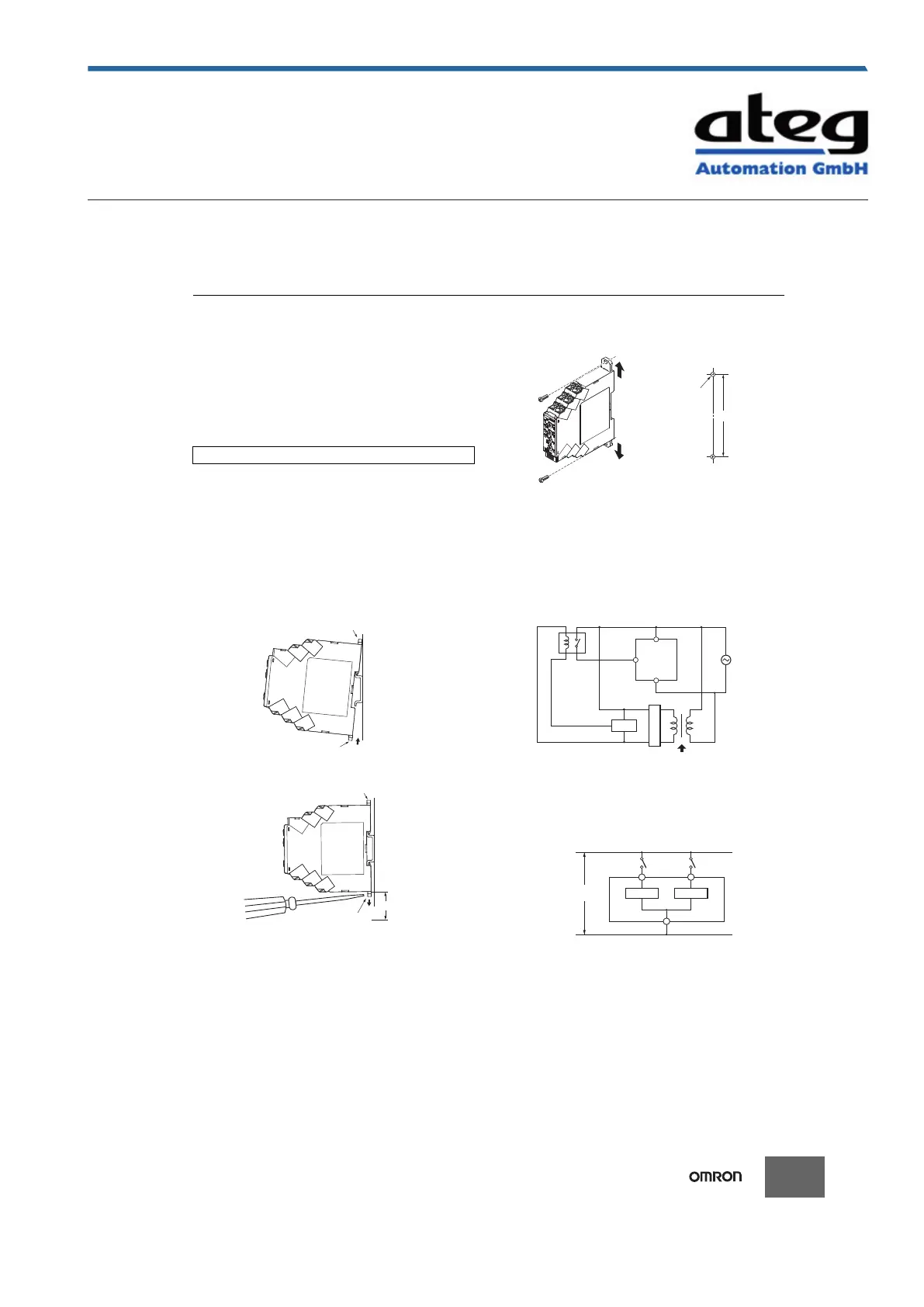
Mounting and Dismounting
• Although there are no particular mounting restrictions, the Timer
should be mounted as horizontally as possible.
• When mounting the Timer on a mounting Track, loosen the two
hooks, press the Timer onto the Track, and then insert the hooks.
• When removing the Timer, pull out the two hooks, and then remove
the Timer from the Track.
• It will be easier to mount and dismount the Timer if a distance of 30
mm or more is provided between the bottom of the Timer and other
equipment.
Screw Mounting
1. Pull out the two hooks on the back of the Timer to the outside until
you hear them click in place.
2. Insert M3 screws into the hook holes and secure the Timer.
Power Supply
• The power supply can be connected to the power input terminals
without considering polarity.
• A DC power supply can be connected if its ripple factor is 20% or
less and the average voltage is within the allowable voltage
fluctuation range of the Timer.
• For the power supply of the input device, use an isolating
transformer in which the primary and secondary windings are
mutually isolated and the secondary winding is not grounded.
(H3DT-N and H3DT-L only)
• The H3DT-H has a large inrush current. Provide sufficient power
supply capacity.
If the power supply capacity is too small, there may be delays in
turning ON the output.
Relationship between Input and Power Supply
Circuits (H3DT-N/L)
• The input circuit and the power supply circuit are configured
independently. The input circuit can be turned ON and OFF without
considering the ON/OFF state of the power supply.
A voltage equivalent to the power supply voltage is also applied to
the input circuit.
Precautions for Correct Use
Hook
Hook
30 mm min.
Hook
Hook
Erstellt am 09.10.2020 um 23:38 Uhr | Alle Angaben ohne Gewähr, Irrtümer und Änderungen vorbehalten! Seite 32 von 37
 Loading...


