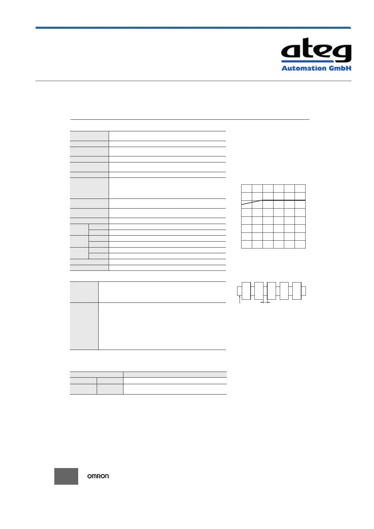
Installation Pitch and Output
Switching Capacity (Reference
Values)
The relation between the installation pitch and
the load current is shown in the following
graph.
If Timer is used under load conditions that
exceed the specified values, the temperature
inside the Timer will increase, reducing the life
expectancy of internal parts.
Applicable standards
* Certification is pending for DNV GL.
Accuracy of operating
time
1% of FS max. (1% 10 ms max. at 1.2-s range)
Setting error 10% of FS 0.05 s max.
Minimum input signal
width
50 ms (start input)
Influence of voltage 0.5% of FS max. (0.5% 10 ms max. at 1.2-s range)
Influence of
temperature
2% of FS max. (2% 10 ms max. at 1.2-s range)
Insulation resistance 100 M min. at 500 VDC
Dielectric strength
Between charged metal part and operating section: 2,900 VAC 50/60 Hz for 1
min.
Between control output terminals and operating circuit: 2,000 VAC 50/60 Hz for
1 min.
Between contacts not located next to each other: 1,000 VAC 50/60 Hz for 1 min.
Impulse withstand
test voltage
5 kV between power terminals, 7.4 kV between conductor terminal and
operating section
Noise immunity
Square-wave noise generated by noise simulator (pulse width: 100 ns/1 s,
1-ns rise): 1.5 kV
Static immunity Malfunction: 4 kV, Destruction: 8 kV
Vibration
resistance
Destruction
0.75-mm single amplitude at 10 to 55 Hz for 2 h each in 3 directions
Malfunction
0.5-mm single amplitude at 10 to 55 Hz for 10 min each in 3 directions
Shock
resistance
Destruction
1,000 m/s
2
3 times each in 6 directions
Malfunction
100 m/s
2
3 times each in 6 directions
Life
expectancy
Mechanical
10 million operations min. (under no load at 1,800 operations/h)
Electrical
100,000 operations min. (5 A at 250 VAC, resistive load at 360 operations/h)
Degree of protection IP30 (Terminal block: IP20)
Weight Approx. 100 g
Safety
standards
cULus: UL 508/CSA C22.2 No. 14
EN 61812-1: Pollution degree 2, Overvoltage category III
CCC: Pollution degree 2, Overvoltage category II, section GB 14048.5
LR: Category ENV1.2
DNV GL *
EMC
(EMI) EN 61812-1
Radiated Emissions: EN 55011 class B
Emission AC Mains: EN 55011 class B
Harmonic Current: EN 61000-3-2
Voltage Fluctuations and Flicker: EN 61000-3-3
(EMS) EN 61812-1
Immunity ESD: EN 61000-4-2
Immunity RF-interference: EN 61000-4-3
Immunity Burst: EN 61000-4-4
Immunity Surge: EN 61000-4-5
Immunity Conducted Disturbance: EN 61000-4-6
Immunity Voltage Dip/Interruption: EN 61000-4-11
Erstellt am 09.10.2020 um 23:38 Uhr | Alle Angaben ohne Gewähr, Irrtümer und Änderungen vorbehalten! Seite 5 von 37
 Loading...


