4
B3FB3F
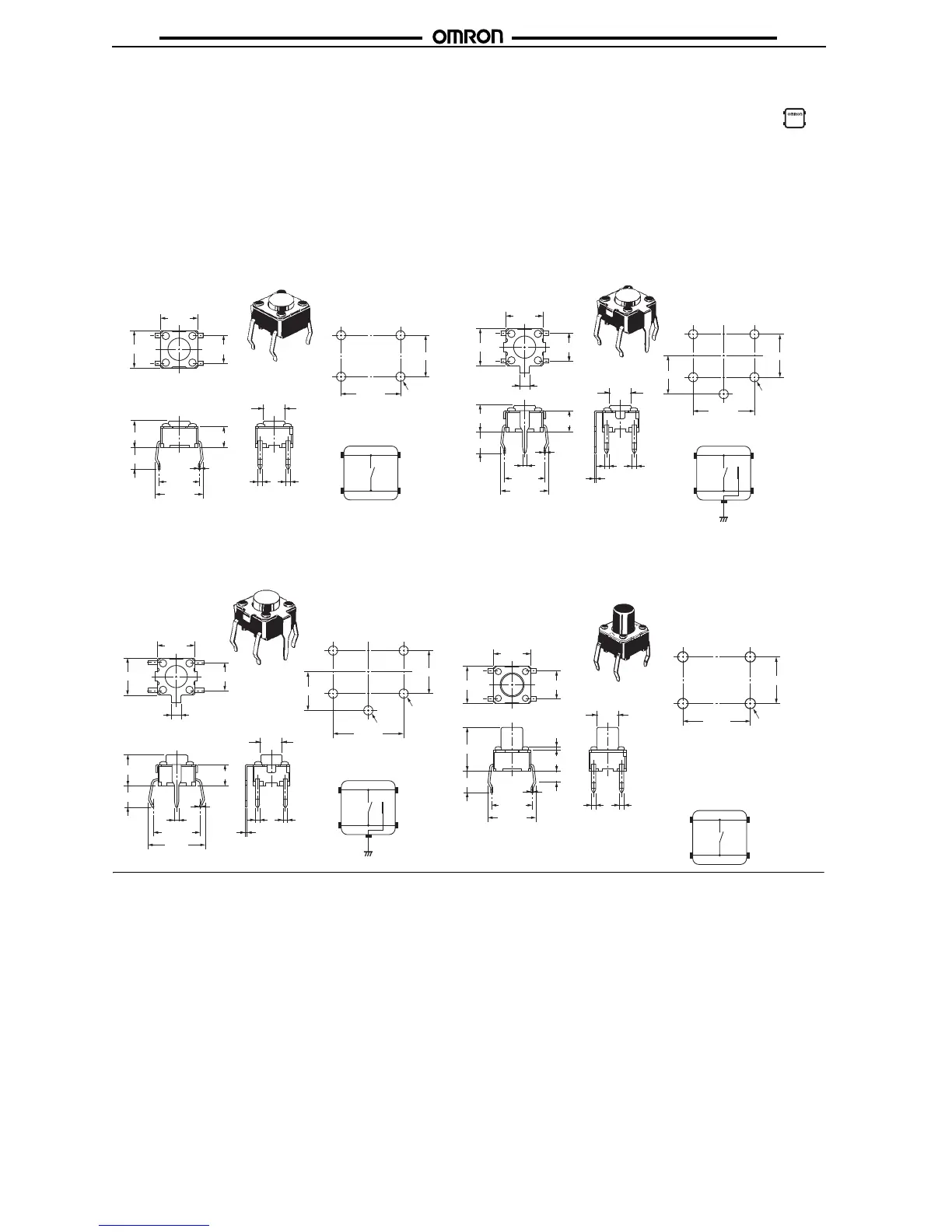
■ Dimensions (Unit: mm)
Note: The numbers used for terminals in the following graphics are indicated in the “Bottom View” diagram below. In this
diagram, the Switch is rotated so that the terminals are on the right and left-hand sides, and the OMRON logo ap-
pears the right way up. (Except Side-operated and Radial Models)
6 × 6 mm Models
Note: Unless otherwise specified, a tolerance of ±0.4 mm applies to all dimensions. No terminal numbers are indicated on the Switches.
B3F-1060, B3F-1062, B3F-1062-G
Terminal Arrangement/
Internal Connections (Top View)
Standard, Flat Plunger Type
(without Ground Terminal)
PCB Mounting (Top View)
(Single-sided PCB, t=1.6)
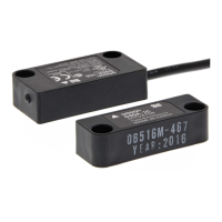
Terminal Arrangement/Internal
Connections (Top View)
Note: The height of B3F-1120, B3F-1122, and
B3F-1125 is 5±0.2 mm.
PCB Mounting (Top View)
(Single-sided PCB, t=1.6)
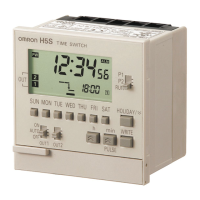
Terminal Arrangement/
Internal Connections
(Top View)
PCB Mounting (Top View)
(Single-sided PCB, t=1.6)
Terminal Arrangement/Internal
Connections (Top View)
Note: The height of B3F-1020, B3F-1022, B3F-1025,
and B3F-1026 is 5±0.2 mm.
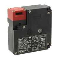
Standard, Flat Plunger Type
(with Ground Terminal, Pitch: 7.5 mm)
B3F-1110
PCB Mounting (Top View)
(Single-sided PCB, t=1.6)
B3F-1100, B3F-1102, B3F-1105
B3F-1120 (See note.), B3F-1122 (See note.)
B3F-1125 (See note.)
B3F-1102-G, B3F-1122-G (See note.)
Standard, Flat Plunger Type
(with Ground Terminal, Pitch: 6.5 mm)
B3F-1000, B3F-1002, B3F-1005, B3F-1006
B3F-1020 (See note.), B3F-1022 (See note.),
B3F-1025 (See note.), B3F-1026 (See note.)
B3F-1002-G, B3F-1022-G (See note.)
Standard, Flat Plunger Type
(without Ground Terminal)
6±0.2
4.3±0.2
3.5
3.4
3.5
dia.
4
2
3
1
0.7 0.7
0.3
6.5
±0.5
7.7±0.5
(See note.)
6±0.2
4.5±0.2
6.5±0.1
4.5±0.1
Four, 1±0.1 dia.
4.3±0.2
3.5
6
±0.2
6±0.2
1.5
0.7
6.5±0.5
7.7±0.5
6.5±0.1
4.5±0.1
4.1±0.1
Five, 1±0.05 dia.
4
2
3
5
1
3.5
dia.
0.7 0.7
0.3
0.3
(See note.)
4.5±0.2
3.4
0.3
0.3
5
±0.2
3.5
0.7
7.5
±0.5
9±0.5
6±0.2
6±0.2
4.5±0.2
1.5
3.5
dia.
0.7 0.7
Four,
1.2
±0.05 dia.
1
±0.05 dia.
7.5
±0.1
4.5±0.1
4.1±0.1
4
2
3
5
1
3.4
6.5±0.5
7.7±0.5
0.7 0.7
4
2
3
1
4.5
±0.2
3.5
dia.
4.5
±0.1
3.4
0.3
(1.8)
0.5 max.
6
±0.2
6.5±0.1
Four,
1
±0.05 dia.
6
±0.2
7±0.2
3.5