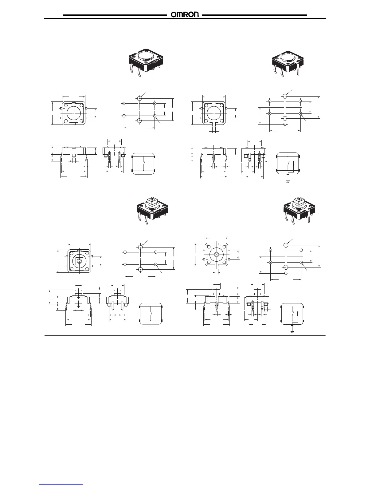
B3F-4000, B3F-4005,
B3F-5000, B3F-5001
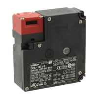
B3F-4100, B3F-4105,
B3F-5100, B3F-5101
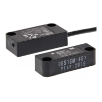
B3F-4050, B3F-4055,
B3F-5050, B3F-5051
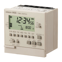
B3F-4150, B3F-4155,
B3F-5150, B3F-5151
Standard, Long-durability,
and High-reliability Models
Flat Plunger Type
(without Ground Terminal)
Standard, Long-durability,
and High-reliability Models
Projected Plunger Type
(without Ground Terminal)
Standard, Long-durability,
and High-reliability Models
Projected Plunger Type
(with Ground Terminal)
Standard, Long-durability,
and High-reliability Models
Flat Plunger Type
(with Ground Terminal)
PCB Mounting (Top View)
(Single-sided PCB, t=1.6)
Terminal Arrangement/
Internal Connections
(Top View)
PCB Mounting (Top View)
(Single-sided PCB, t=1.6)
Terminal Arrangement/
Internal Connections
(Top View)
PCB Mounting (Top View)
(Single-sided PCB, t=1.6)
Terminal Arrangement/
Internal Connections
(Top View)
PCB Mounting (Top View)
(Single-sided PCB, t=1.6)
Terminal Arrangement/
Internal Connections
(Top View)
12±0.2
5±0.2
5±0.1
Four,
1.2
±0.05 dia.
9
±0.1
12±0.2
12.5±0.1
4
2
3
1
Two, 1.8
±0.05 dia.
(for positioning boss)
5
±0.1
6.9±0.1
Five,
1.2
±0.05 dia.
Two, 1.8
±0.05
dia.
(for positioning boss)
9±0.1
12±0.2
5±0.2
1.6
12
±0.2
12.5±0.1
4
2
3
5
1
12±0.2
5±0.2
12±0.2
4
2
3
1
5
±0.1
Four,
1.2
±0.05 dia.
9
±0.1
12.5±0.1
Two, 1.8±0.05 dia.
(for positioning boss)
12
±0.2
5±0.2
1.6
12
±0.2
4
2
3
5
1
5
±0.1
6.9±0.1
Five,
1.2
±0.05 dia.
Two, 1.8
±0.05
dia.
(for positioning boss)
9±0.1
12.5±0.1
0.3 11
3.5
7.1 dia.
12.5
±0.5
1.6 dia.
9
±0.1
13.8
±0.5
4.3
±0.2
3.5
1
6.9
1
7.1 dia.
9
±0.1
4.3
±0.2
3.5
0.30.9
3.5
12.5
±0.5
13.8
±0.5
1.6 dia.
@3.8
±0.1
11
7.1 dia.
9
±0.1
4.3
±0.2
7.3
±0.2
3.5
0.3
3.5
1.8
±0.2
12.5
±0.5
13.8
±0.5
1.6 dia.
@3.8
±0.1
7.1 dia.
7.3
±0.2
4.3
±0.2
3.5
0.30.9
3.5
1.8
±0.2
12.5
±0.5
13.8
±0.5
1
6.9
1
9
±0.1
1.6 dia.