Appendix BSpecifications
175
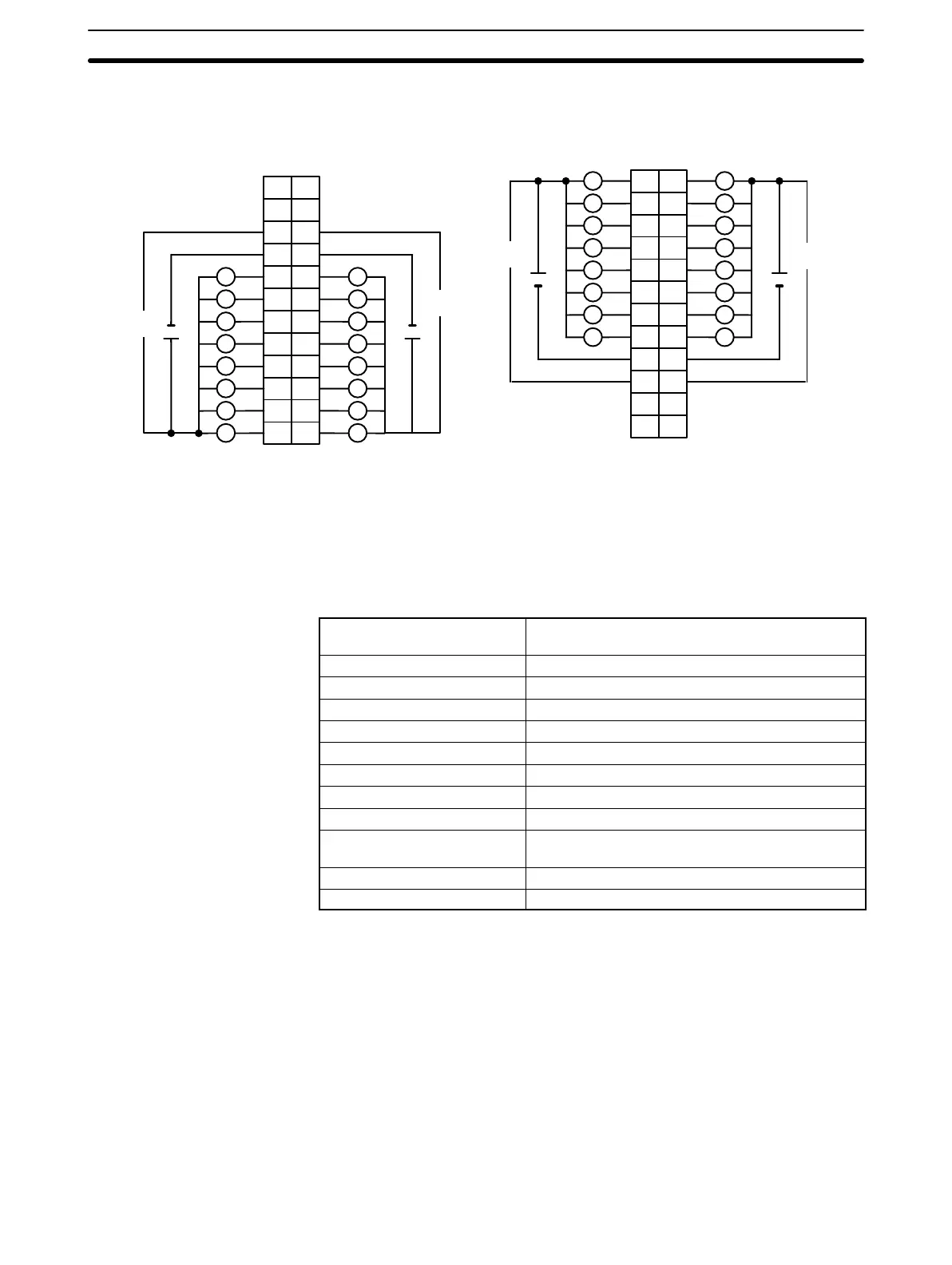
Terminal Connections
I/O word “n”
CN1
I/O word “n+1”
CN2
L L
L
+5 to 24 VDC +5 to 24 VDC
B
1
2
3
4
5
6
7
8
9
0
1
2
3
4
5
6
7
COM0
+
10
NC
11
NC
8
9
10
11
12
13
14
15
COM1
+
AB
0
1
1
2
2
3
3
4
4
5
5
6
6
7
7
8
COM2
9
8
9
10
11
12
13
14
15
COM3
10
NC
11
NC
NC
12
A
1
2
3
4
5
6
7
8
9
10
11
12
NC
NC
12
NC
1
2
3
4
5
6
7
8
9
10
11
12
5 to 24
VDC
5 to 24
VDC
5 to 24
VDC
5 to 24
VDC
L
L
L
L
L
L
L
L
L
L
L
L
L
L
L
+ +
+5 to 24 VDC+5 to 24 VDC
LL
L L
L L
L L
L L
L L
L L
Note 1. I/O word “n” is determined by the unit number setting (n = IR 100 + 10 × unit number).
2. The Unit will have 32 static output points when pin 1 of it’s DIP switch is OFF.
3. When wiring output circuits, be sure to use the correct polarity for the external power supplies. Wiring
with incorrect polarity may result in erroneous operation of the load.
Transistor Output Unit C200H-OD215
(Used as 128-point Dynamic Output Unit)
Max. Switching Capacity 16 mA, 4.5 VDC to 100 mA, 26.4 VDC
800 mA/common, 3.2 A/Unit
Min. Switching Capacity None
Leakage Current 0.1 mA max.
Residual Voltage 0.7 V max.
ON Response Time 0.2 ms max.
OFF Response Time 0.6 ms max.
No. of Circuits 2 (dynamic, 64 points/circuit)
Internal Current Consumption 220 mA 5 VDC max.
Fuses 4 (1 fuse/common; fuses are not user-replacable.)
Power for External Supply
90 mA 5 to 24 VDC10% min.
(2.8 mA × number of ON outputs)
Weight 300 g max.
Dimensions 130×34.5×100.5 (H×W×D, in millimeters)
 Loading...


