9
Program
9.1.1. Outline of Processing
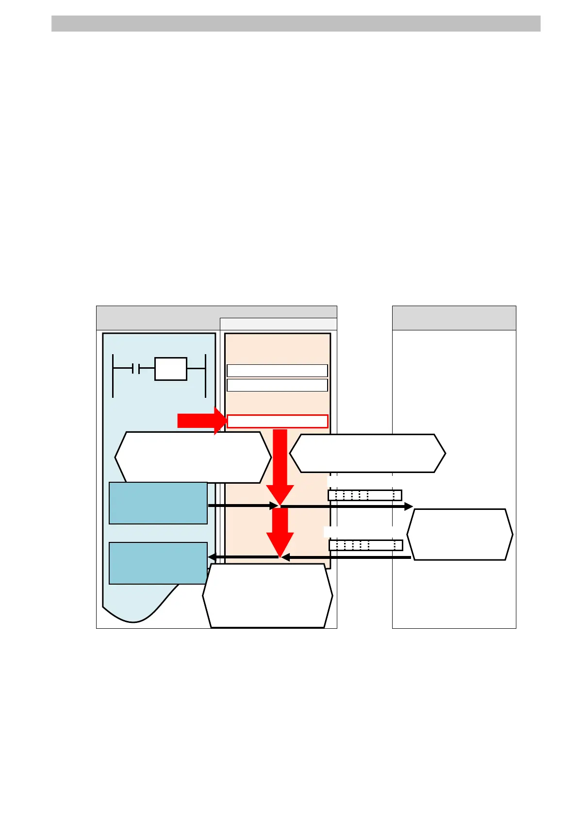
The following figure shows the data flow from when PLC (SCU) issues command data to
Destination Device using serial communications until PLC receives response data from
Destination Device.
(1)The ladder program specifies the communications sequence No. 900 and executes the
PMCR instruction.
(2) The PLC receives the response data from Sensor Controller according to receive
messages defined by the communications sequence No. 900 and stores them in the
response data storage area.
(3)The Sensor Controller executes the command by receiving the command data from PLC,
and returns response data to PLC.
(4)The PLC receives the response data from Sensor Controller according to the receive
messages defined by the communications sequence No. 900, and stores them in the
response data storage area.
RS-232C Sensor Controller
Ladder program
data.
5501 onwards
Response data
response data and
stores them in the
specified memory.
instruction.
(Specifying the sequence No.
command and
returns the
5020 onwards
Send data

 Loading...


