16
CJ1M-CPU22/23 Specifications
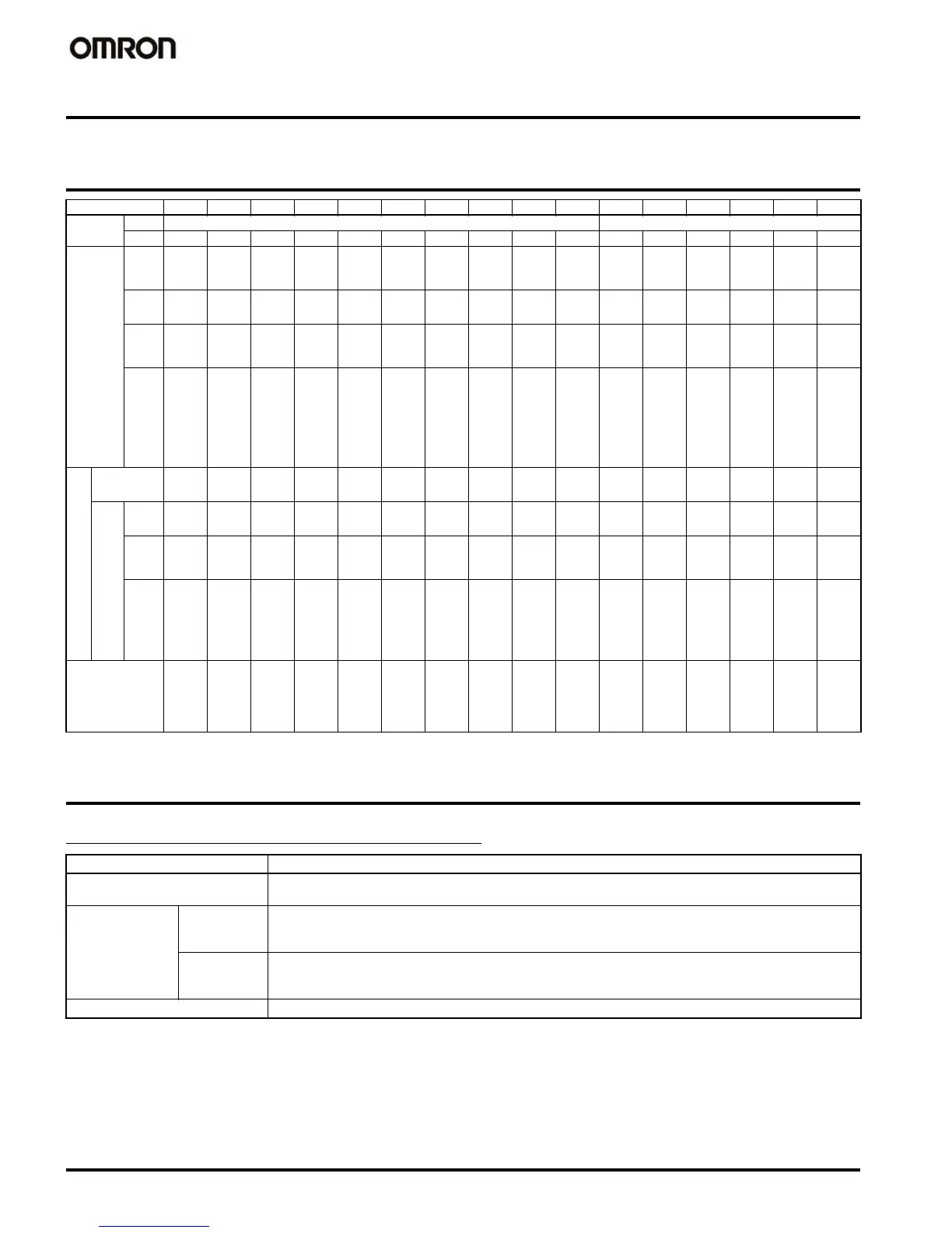
Built-in I/O Allocation Areas
Built-in Input Specifications
Interrupt Inputs and Quick-response Inputs
I/O point IN0 IN1 IN2 IN3 IN4 IN5 IN6 IN7 IN8 IN9 OUT1 OUT2 OUT3 OUT4 OUT5 OUT6
Word 2960 2961
Bit0123456789012345
Input Gener-
al-pur-
pose
input
General-
purpose
input 0
General-
purpose
input 1
General-
purpose
input 2
General-
purpose
input 3
General-
purpose
input 4
General-
purpose
input 5
General-
purpose
input 6
General-
purpose
input 7
General-
purpose
input 8
General-
purpose
input 9
------
Inter-
rupt in-
put
Interrupt
input 0
Interrupt
input 1
Interrupt
input 2
Interrupt
input 3
------------
Quick-
re-
sponse
input
Quick-
re-
sponse
input 0
Quick-
re-
sponse
input 1
Quick-
re-
sponse
input 2
Quick-
re-
sponse
input 3
------------
High-
speed
counter
input
- - High-
speed
counter
input 1
(phase Z
or reset)
High-
speed
counter
input 0
(phase Z
or reset)
- - High-
speed
counter
input 1
(phase A
incre-
mental,
or count
input)
High-
speed
counter
input 1
(phase B
decre-
mental,
or direc-
tion in-
put)
High-
speed
counter
input 0
(phase A
incre-
mental,
or count
input)
High-
speed
counter
input 0
(phase B
decre-
mental,
or direc-
tion in-
put)
------
Out-
put
General-pur-
pose output
----------General-
purpose
output 0
General-
purpose
output 1
General-
purpose
output 2
General-
purpose
output 3
General-
purpose
output 4
General-
purpose
output 5
Pulse
output
CW/
CCW
----------Pulse
output 0
(CW)
Pulse
output 0
(CCW)
Pulse
output 1
(CW)
Pulse
output 1
(CCW)
--
Pulse +
direc-
tion
----------Pulse
output 0
(pulse)
Pulse
output 1
(pulse)
Pulse
output 0
(direc-
tion)
Pulse
output 1
(direc-
tion)
--
Pulse
with
vari-
able
duty
factor
(PWM)
output
--------------PWM
output 0
PWM
output 1
Origin search Origin
search 0
(origin
input sig-
nal)
Origin
search 0
(origin
proximi-
ty input
signal)
Origin
search 1
(origin
input sig-
nal)
Origin
search 1
(origin
proximi-
ty input
signal)
Origin
search 0
(posi-
tioning
comple-
tion sig-
nal)
Origin
search 1
(posi-
tioning
comple-
tion sig-
nal)
--------Origin
search 0
(error
counter
reset
output)
Origin
search 1
(error
counter
reset
output)
Item Specification
Number of interrupt and quick-re-
sponse input points
4 total
Interrupt inputs Interrupt in-
put mode
At the rising or falling edge of the input signal, the CPU Unit’s cyclic program is interrupted and the corre-
sponding I/O interrupt task (task number 140 to 143) is executed. The response time (i.e., the time from the
input condition being satisfied until execution of the interrupt task) is 93
µs min.
Counter
mode
The number of rising or falling edges of the input signal are counted incrementally or decrementally, and
when the count has been reached, the corresponding interrupt task (task number 140 to 143) is executed.
The input response frequency is 1 kHz.
Quick-response input Signals less than the cycle time (30
µs min.) can be treated as ON signals for one cycle.