18
Pulse with Variable Duty Factor (PWM) Output Function
Hardware Specifications
Input Specifications
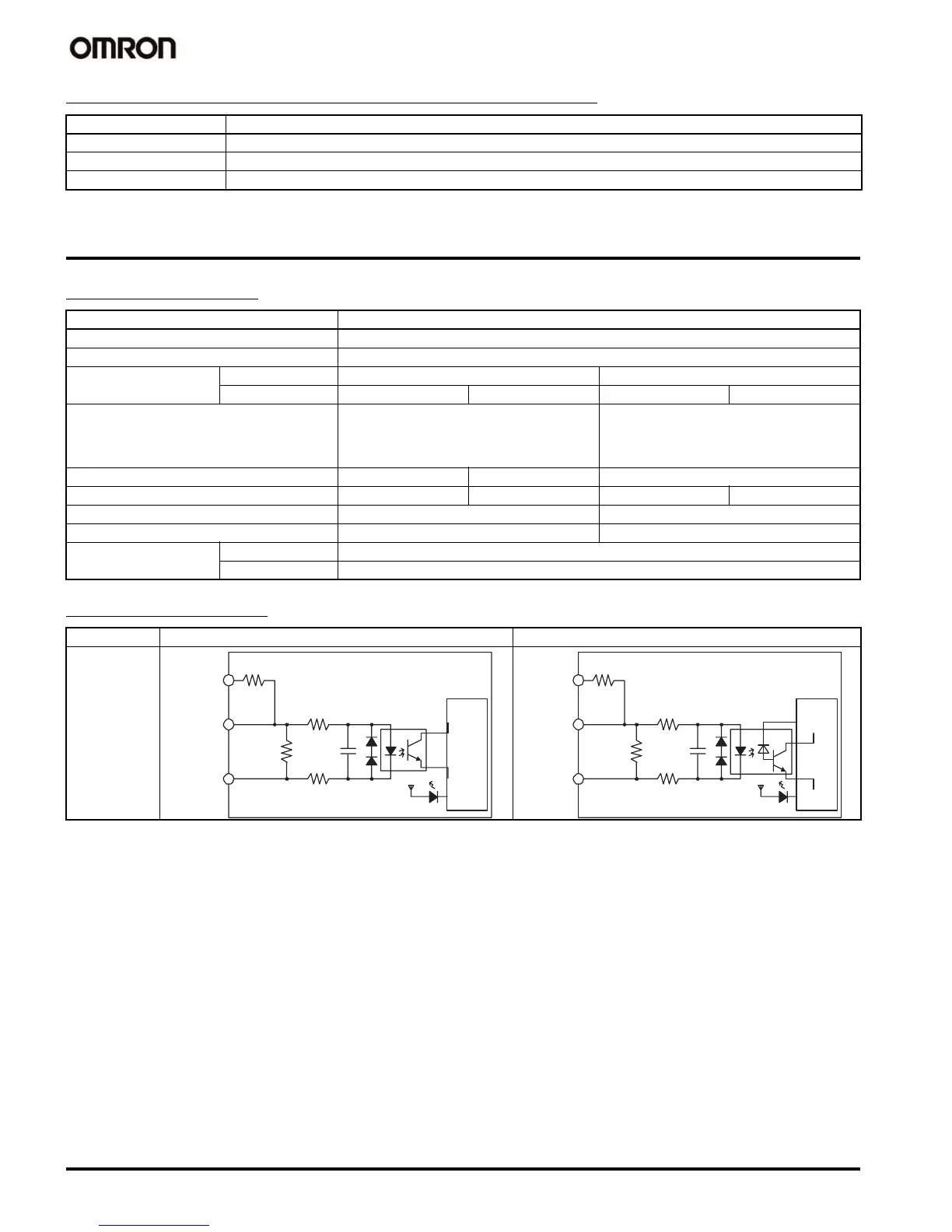
Circuit Configuration
Item Specification
Duty ratio 0% to 100%, set in 1% units
Frequency 0.1 to 999.9 Hz, set in 0.1-Hz units
Instruction for PWM PWM (PULSE WITH VARIABLE DUTY FACTOR): Used to output pulses with the specified duty factor.
Item Specification
Number of input points 10 points
Input type 24-VDC input or line driver input (switched with wiring)
24-VDC input Line driver input
Input points IN0 to IN5 IN6 to IN9 IN0 to IN5 IN6 to IN9
Input voltage 20.4 to 26.4 VDC Conforms to RS-422 line driver (equivalent to
AM26LS31).
The power supply voltage on the connected
side must be 5 V
±5%.
Input impedance 3.6 k
Ω 4.0 kΩ
Input current (typ.) 6.2 mA 4.1 mA 13 mA 10 mA
ON voltage (min.) 17.4 VDC min./3 mA min. -
ON voltage (max.) 5.0 VDC/1 mA max. -
Response speed (for
general-purpose input)
ON response time 8 ms max. (Select 0, 0.05, 1, 2, 4, 8, 16, or 32 ms in PC Setup.)
OFF response time 8 ms max. (Select 0, 0.05, 1, 2, 4, 8, 16, or 32 ms in PC Setup.)
Input IN0 to IN5 IN6 to IN9
Circuit
configuration
24 V
LD+
0 V/LD−
100 Ω
1000 pF
100 Ω
750 Ω
3.6 kΩ
Internal circuit
24 V
LD+
0 V/LD−
100 Ω
1000 pF
100 Ω
1.5 KΩ
4.0 kΩ
Internal circuit