A--33
Micro Programmable Controller
CPM1A
J COMMUNICATIONS ADAPTER
RS-232C Adapter and RS-422 Adapter
CPM1-CIF01 CPM1-CIF11
Model
CPM1-CIF01 CPM1-CIF11
Functions Level conversion between the CMOS level
(CPU side) and the RS-232C (peripheral
device side)
Level conversion between the CMOS level
(CPU side) and the RS-422 (peripheral device
side)
Insulation The RS-232C (peripheral device side) is insu-
lated by a DC/DC converter and photocoupler.
The RS-422 (peripheral device side) is insu-
lated by a DC/DC converter and photocoupler.
Power supply Power is supplied by the CPU.
Power consumption 0.3 A max.
Transmission speed 38.4 kbits/s max.
Vibration resistance 10 to 57 Hz with an amplitude of 0.075 mm, and 57 to 150 Hz with an acceleration of 1 G in the X,
Y and Z directions for 80 minutes each (i.e. for 8 minutes each, 10 times).
Shock resistance 1.5 G in the X, Y and Z directions 3 times each.
Ambient temperature
Operating 0°Cto55°C(32°F to 131°F) 0°Cto55°C(32°F to 131°F)
Storage -- 2 0 °Cto75°C(--4°F to 167°F) -- 2 0 °Cto75°C(--4°F to 167°F)
Ambient humidity Operating 10% to 90% RH (with no condensation)
Ambient environment Operating With no corrosive gas
Weight 200 g max.
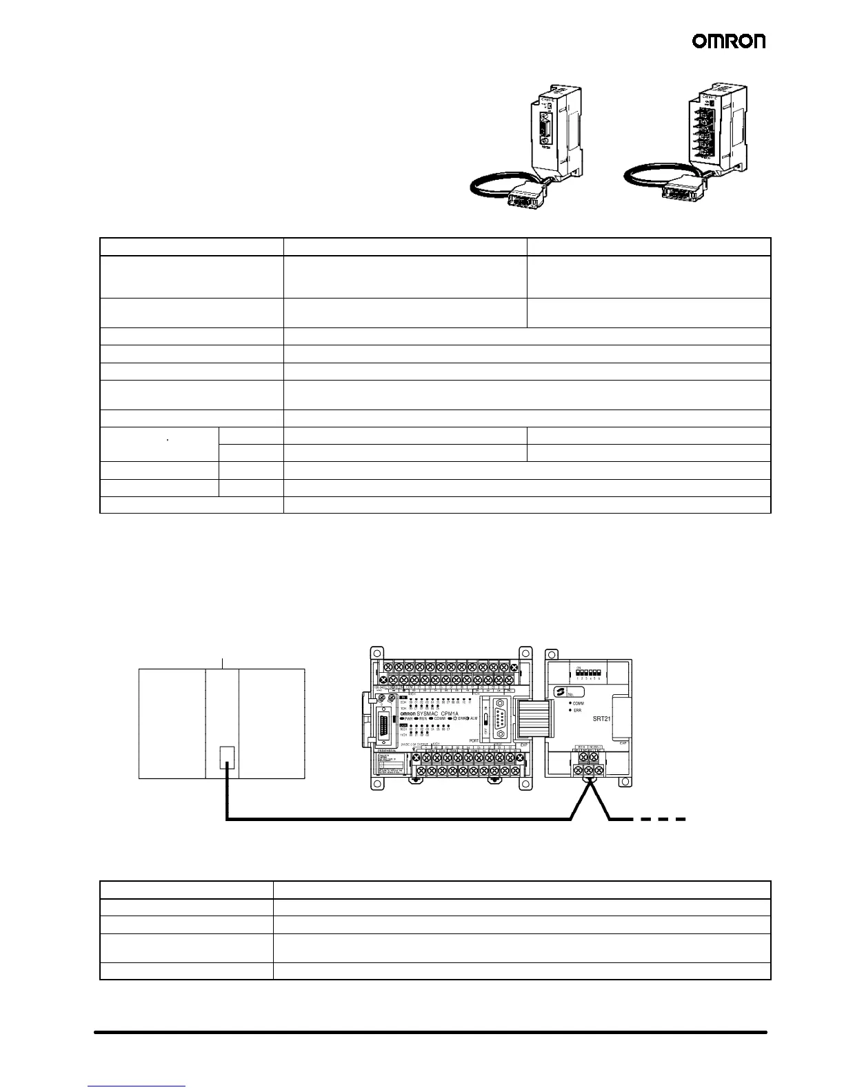
J COMPOBUS/S I/O LINK MODULE
The CPM1A controller can function as a Slave to a CompoBus/S Master Module (or SRM1 CompoBus/S Master Control Module) when a
CPM1A-SRT21 CompoBus/S I/O Link Module is connected. The CompoBus/S I/O Link Module establishes an I/O link of 8 inputs and 8
outputs between the Master Module and the CPM1A. Up to 3 Expansion I/O Modules or Expansion Modules can be connected to a
CPM1A CPU.
CS1
j
, C200H
j
,
CQM1 (H), or CJ1 (M),
CPM2C-S
Up to 16 Slaves can be connected.
(Up to 8 Slaves with the CQM1-SRM21-V1.)
CompoBus/S Master Module
(or SRM1 CompoBus/S Master
Control Module)
CPM1A CPU
CPM1A-SRT21
CompoBus/S I/O
Link Module
Flat cable SCA1-4F10 or twisted
pair Belden #9409 cable
Specifications
Model CPM1A-SRT21
Master/Slave CompoBus/S Slave
Number of I/O bits 8 input bits, 8 output bits
Number of words occupied in
CPM2A I/O memory
1 input word, 1 output word
(Allocated in the same way as other Expansion I/O Modules or Expansion Modules)
Node number setting Set using the DIP switch.
Note: See the CompoBus/S section of Omron’s Remote I/O and Wiring Solutions Catalog (GC RIO1) for more details on CompoBus/S
communications.

 Loading...


