A--28
Micro Programmable Controller
CPM1A
J I/O SPECIFICATIONS
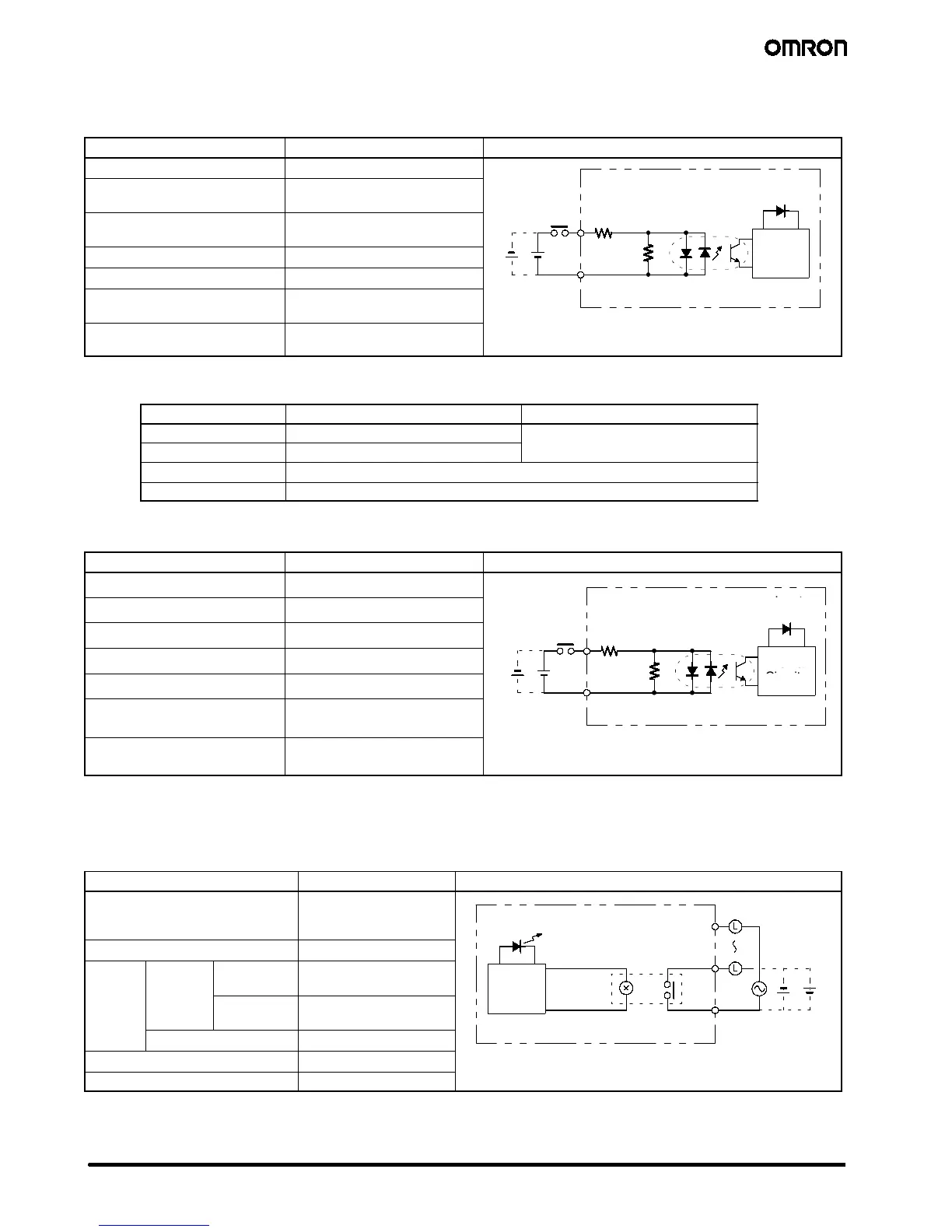
CPU DC Input
Item Specifications Circuit
Input voltage 24 VDC
+10%
/
--15%
Input impedance IN0000 to IN0002: 2 kΩ
Others: 4.7 kΩ
Input
LED
Input current (typical) IN0000 to IN0002: 12 mA
Others: 5 mA
4.7 kΩ
ON voltage 14.4 VDC min.
Circuits
4.7 kΩ
OFF voltage 5.0 VDC max.
ON delay (See Note 1) 1 to 128 ms max.
(default: 8 ms) (See Note 1)
OFF delay (See Note 1) 1 to 128 ms max.
(default: 8 ms) (See Note 1)
either positive or negative.
Note: 1. The actual ON/OFF delay includes an input constant of 1, 2, 4, 8, 16, 32, 64, or 128 ms (default: 8 ms).
2. When IN0000 to IN0006 are used for the high-speed counter inputs, the delays are as shown below:
Input
Increment mode Differential phase mode
IN0000 (A-phase) 5kHz
2.5 kHz
IN0001 (B-phase) Normal input
IN0002 (Z-phase) ON: 100 µs max. OFF: 500 µsmax.
IN0003 to IN0006 0.3 ms max. (From the time of input ON until the interrupt subroutine is executed.)
Expansion I/O Unit
Item Specifications Circuit
Input voltage 24 VDC,
+10%
/
-- 1 5 %
Input impedance 4.7 kΩ
Input
LED
Input current (typical) 5mA
4.7 kΩ
ON voltage 14.4 VDC min.
Internal
IN
OFF voltage 5.0 VDC max.
COM
Circuits
ON delay 1 to 128 ms max.
(default: 8 ms) (See Note)
OFF delay 1 to 128 ms max.
(default: 8 ms) (See Note)
either positive or negative.
Note: The actual ON/OFF delay includes an input constant of 1, 2, 4, 8, 16, 32, 64, or 128 ms (default: 8 ms).
J OUTPUT SPECIFICATIONS (CPU AND EXPANSION I/O MODULES)
Relay Output
Item Specifications Circuit
Maximum switching capacity 2 A, 250 VAC (cos φ =1)
2A,24VDC
(4 A/common)
OUT
Output
LED
Minimum switching capacity 10 mA, 5 VDC
Relay
service
Electrical
Resistance
load
150,000 times
OUT
Internal
life
Inductive
load
100,000 times
Mechanical 20 million times
ON delay 15 ms max.
250 VAC: 2 A
OFF delay 15 ms max.

 Loading...


