36
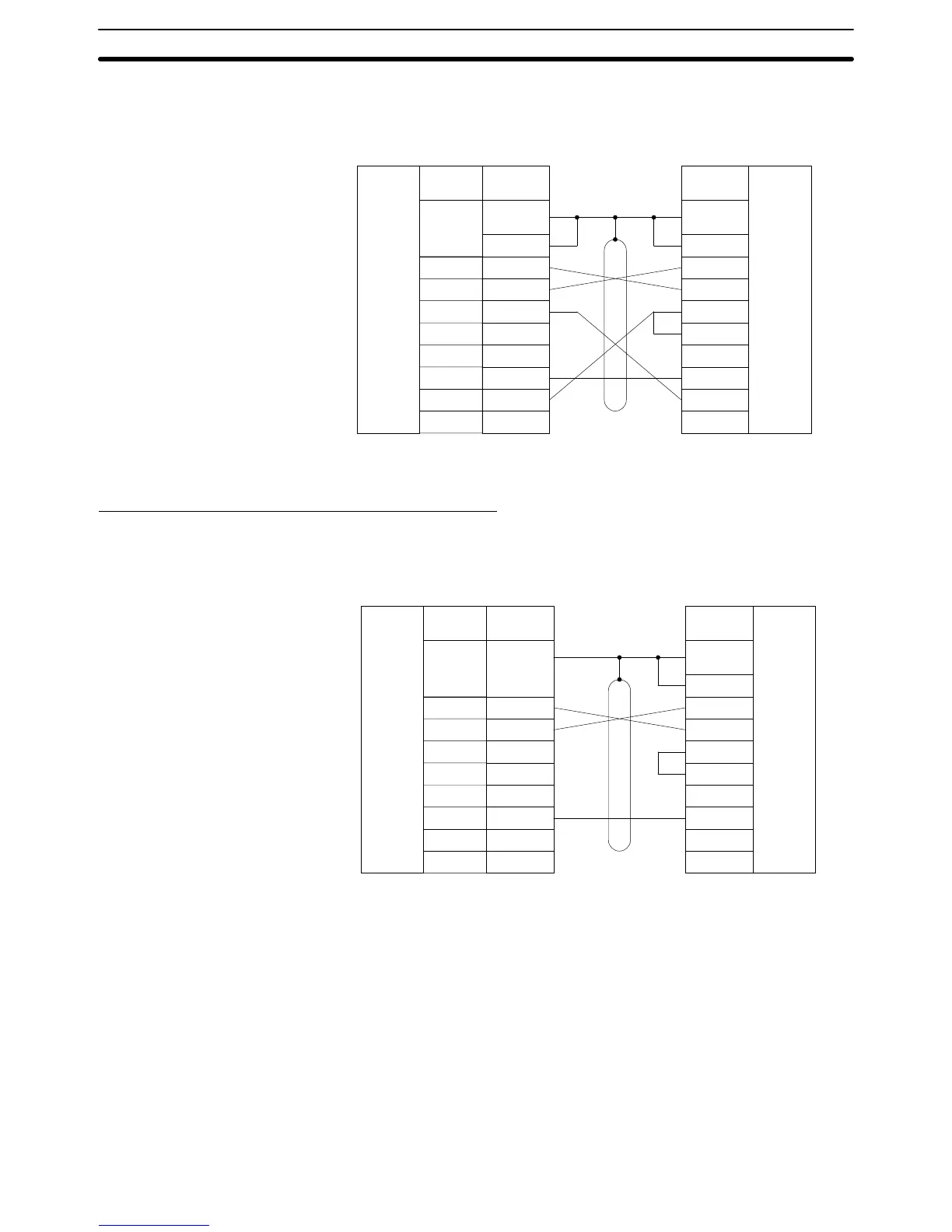
Half Duplex The following diagram shows 1-to-1 host link connections using communica-
tions port 1 in half duplex. Half-duplex communications must be set using the
Host Link Unit’s CPU Bus Unit System Setup.
Signal
name
SD (TXD)
RD (RXD)
RS (RTS)
CS (CTS)
SG (GND)
2
3
4
5
7
FG
CD (DCD) 8
RS-232C
interface
Pin
number
2
3
4
5
6
7
8
20
RS-232C
interface
1
Pin
number
Host Link Unit Host computer
Connector
hood
Shield
1
Connector
hood
Note The CTS selector of the Host Link Unit must be turned ON (fixed to 0 V).
Communications via Communications Port 2
The following diagram shows 1-to-1 host link connections using communica-
tions port 2 in full duplex. Full-duplex communications must be set using the
Host Link Unit’s CPU Bus Unit System Setup.
Signal
name
SD (TXD)
RD (RXD)
RS (RTS)
CS (CTS)
SG (GND)
2
3
4
5
9
FG
CD (DCD) 7
RS-232C
interface
Pin
number
2
3
4
5
6
7
8
20
RS-232C
interface
1
Pin
number
Host Link Unit Host computer
Connector
hood
Shield
Connector
hood
Full Duplex
1-to-1 Connection Examples Section 3-6