D4N
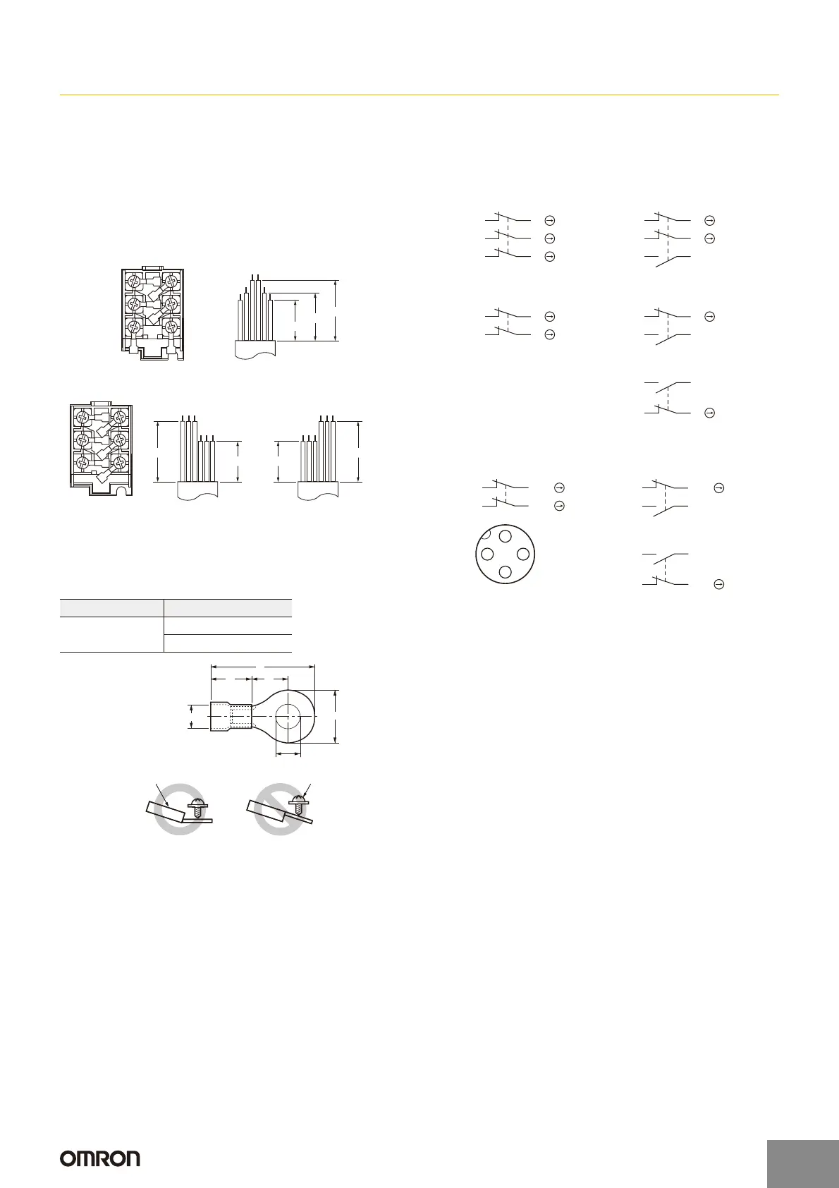
Wiring
Wiring
x When connecting to the terminals via insulating tube and M3.5
crimp terminals, arrange the crimp terminals as shown below so
that they do not rise up onto the case or the cover.
Applicable lead wire size: AWG20 to AWG18 (0.5 to 0.75 mm
2
).
Use lead wires of an appropriate length, as shown below. Not
doing so may result in excess length causing the cover to rise and
not fit properly.
One-conduit Type (3 Poles)
Two-conduit Type (3 Poles)
x Do not push crimp terminals into gaps in the case interior. Doing so
may cause damage or deformation of the case.
x Use crimp terminals not more than 0.5 mm in thickness. Otherwise,
they will interfere with other components inside the case.
[Reference] The crimp terminals shown below are not more than
0.5 mm thick.
Contact Arrangement
x The contact arrangements are shown below.
Screw Terminal Type
Connector Type
x Applicable socket: XS2F (OMRON).
x Refer to the Connector Catalog for details on socket pin numbers
and lead wire colors.
Socket Tightening (Connector Type)
x Turn the socket connector screws by hand and tighten until no
space remains between the socket and the plug.
x Make sure that the socket connector is tightened securely.
Otherwise, the rated degree of protection (IP67) may not be
maintained and vibration may loosen the socket connector.
Conduit Opening
x Connect a recommended connector to the opening of the conduit
and tighten the connector to the specified torque. The case may be
damaged if an excessive tightening torque is applied.
x When using 1/2-14NPT, wind sealing tape around the joint
between the connector and conduit opening so that the enclosure
will conform to IP67.
x Use a cable with a suitable diameter for the connector.
x Attach and tighten a conduit cap to the unused conduit opening
when wiring. Tighten the conduit cap to the specified torque. The
conduit cap is provided with the Switch (2-conduit types).
Changing the Lever
The lever mounting screws can be used to set the lever position to
any position in a 360q angle at 7.5q increments. Grooves are incised
on the lever and rotary shaft that engage to prevent the lever from
slipping against the rotary shaft. The screws on adjustable roller lever
models can also loosened to change the length of the lever.
Remove the screws from the front of the lever before mounting the
lever in reverse (front/back), and set the level so that operation will be
completed before exceeding a range of 180q on the horizontal.
Manufacturer Type
J.S.T. Mfg. Co.
FN0.5-3.7 (F Type)
N0.5-3.7 (Straight Type)
2221
3433
12
11
A
A
C
E
B
D
F
C
E
B
D
F
28 mm
Tolerance ±2 mm
33 mm
42 mm
2221
3433
12
11
A
C
E
B
D
F
ACE
BDF
28 mm
Tolerance ±2 mm
Left hand
42 mm
ACE
BDF
28 mm
Tolerance ±2 mm
Right hand
42 mm
L
l F
B
D dia.
dz dia.
Correct Incorrect
Terminal screw
Crimp terminal
t: 0.5 mm
dz dia.: 3.7 mm
D dia.: 2.9 mm
B: 6.6 mm
L: 19 mm
F: 7.7 mm
I: 8.0 mm
14
32
13
31
D4N-@D@@ (3NC)
11
21
12
22
31 32
D4N-@B@@ (2NC)
D4N-@2@@ (2NC (SNAP))
11
31
12
32
D4N-@C@@ (2NC/1NO)
D4N-@F@@ (2NC/1NO (MBB))
D4N-@A@@ (1NC/1NO)
D4N-@E@@ (1NC/1NO (MBB))
33 34
11
21
12
22
11
33
12
34
D4N-@1@@ (1NC/1NO (SNAP))
14 (4)
32 (2)
(3) 13
(1) 31
1
3
24
Pin No. (Terminal No.)
D4N-9B@@ (2NC)
D4N-92@@ (2NC (SNAP))
D4N-9A@@ (1NC/1NO)
D4N-9E@@ (1NC/1NO (MBB))
(1) 11
(3) 31
12 (2)
32 (4)
(1) 11
(3) 33
12 (2)
34 (4)
D4N-91@@ (1NC/1NO (SNAP))
http://www.ia.omron.com/
19
(c)Copyright OMRON Corporation 2007 All Rights Reserved.

 Loading...