5
DRT2-ID16/OD16
DRT2-ID16/OD16
For more information, contact an Omron representative at 1-800-55-OMRON
■
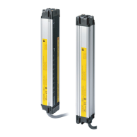
Network Power Voltage Monitor
Function
The network power voltage status and the I/O power status
can be understood at a glance via the network.
The network power voltage is recorded in the Slave (network
power voltage monitor function). It is also possible to detect
whether the I/O power supply is turned ON, and to output a warn-
ing if it is not (I/O power status monitor function). This means that
the status of the network power voltage and I/O power supply for
each SmartSlave can be confirmed at a glance from the Configu-
rator, contributing to reductions in startup time.
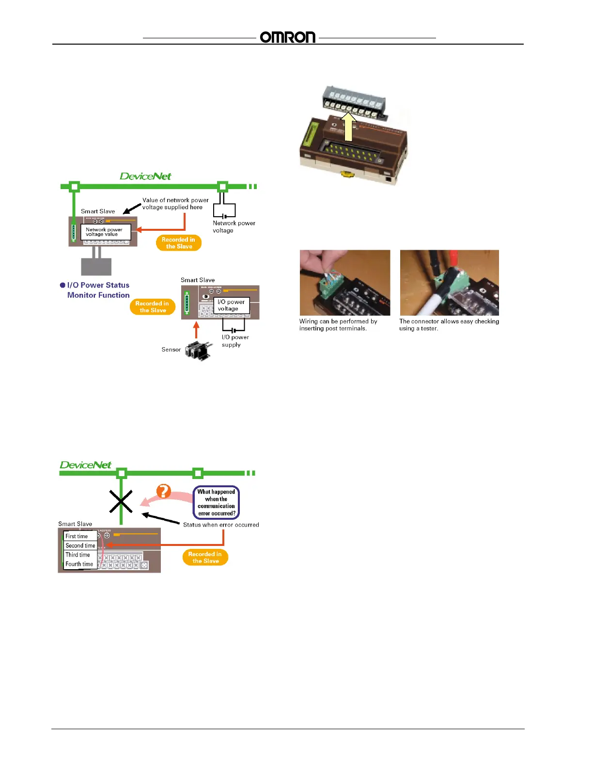
■
Communication Error History Monitor
Function
Causes for communications errors can be monitored.
Information (i.e., communication error code and network power
voltage at the time) for four previous errors can be recorded in the
Slave. This error history can be read from Smart Slaves that are
removed from the network when correcting an error, enabling
more effective maintenance.
■
Improved Structural Flexibility
Smallest in Its Class
The width of the Basic Unit is 115 mm (77% of 150-mm DRT1-
series models) and the width of the Expansion Unit is 94 mm, giv-
ing a total expanded width of 209 mm, making it the smallest
device of its class in the industry.
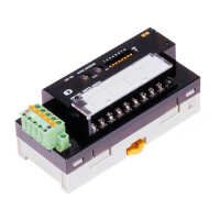
Easy Mounting and Dismounting of Terminal Blocks
Terminal blocks can be mounted and dismounted with ease.
Easy Expansion with Expansion Units
The Smart Slaves can be expanded easily by freely combining
Expansion Units with Basic Units using snap-on mounting. This
means less wiring work is required.
Clamp-type Communications Connectors
Input Filter Function
The influence of noise can be removed using the ON response
time. Also, very small pulses that are shorter than the communica-
tions time can be handled using the OFF response time.
Function for Handling Sensor Inrush Current
In order to prevent incorrect input due to inrush current when, for
example, power to a sensor is turned ON, the Slave can be set not
to accept input for 100 ms after input supply is turned ON.
 Loading...