7
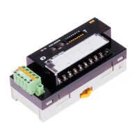
DRT2-ID16/OD16
DRT2-ID16/OD16
For more information, contact an Omron representative at 1-800-55-OMRON
Installation
■ Internal Circuit Diagrams
Remote I/O Terminals (Models with 16 Transistor Inputs)
DRT2-ID16 (NPN)/DRT2-ID16-1 (PNP)
Remote I/O Terminals (Models with 16 Transistor Inputs)
DRT2-OD16 (NPN)/DRT2-OD16-1 (PNP)
Remote I/O Terminals Expansion Units (Models with 8
Transistor Inputs)
XWT-ID08 (NPN)/ID08-1 (PNP)
Remote I/O Terminals Expansion Units (Models with 8
Transistor Outputs)
XWT-OD08 (NPN)/OD08-1 (PNP)
Remote I/O Terminal Expansion Units (Models with 16
Transistor Inputs)
XWT-ID16 (NPN)/ID16-1 (PNP)
Remote I/O Terminal Expansion Units (Models with 16
Transistor Outputs)
XWT-OD16 (NPN)/OD16-1 (PNP)
■
Wiring Diagrams
Remote I/O Terminals (Models with 16 Transistor Inputs)
DRT2-OD16 (NPN)/DRT2-ID16-1 (PNP)
Remote I/O Terminals (Models with 16 Transistor Outputs)
DRT2-ID16 (NPN)/DRT2-OD16-1 (PNP)
Remote I/O Terminal Expansion Units (Models with 8
Transistor Inputs)
XWT-ID08 (NPN)/ID08 (PNP)
Remote I/O Terminal Expansion Units (Models with 8
Transistor Outputs)
XWT-OD08 (NPN)/OD08-1 (PNP)
Remote I/O Terminal Expansion Units (Models with 16
Transistor Inputs)
XWT-ID16 (NPN)/ID16-1 (PNP)
Remote I/O Terminal Expansion Units (Models with 16
Transistor Outputs)
XWT-OD16 (NPN)/OD16-1 (PNP)
DRT2-ID16-1 (PNP)DRT2-ID16 (NPN)
V 24 VDC
0
1
G
V+
CAN H
DRAIN
CAN L
V–
Photocoupler
Photocoupler
Photocoupler
Photocoupler
V 24 VDC
0
1
G
Physical layer
Non-insulated
DC-DC
converter
Non-insulated
DC-DC
converter
V+
CAN H
DRAIN
CAN L
V–
Internal circuit
Physical layer
Internal circuit
DRT2-OD16 (NPN)
DRT2-OD16-1 (PNP)
Photocoupler Photocoupler
Photocoupler
Photocoupler
Physical layer
Physical layer
Non-insulated
DC-DC
converter
Non-insulated
DC-DC
converter
0
1
G
V 24 VDC
V+
CAN H
DRAIN
CAN L
V–
0
1
G
V 24 VDC
V+
CAN H
DRAIN
CAN L
V–
Internal circuit
Internal circuit
Voltage
step-
down
Voltage
step-
down
XWT-ID08 (NPN)
XWT-ID08-1 (PNP)
Photocoupler
Photocoupler
Photocoupler
Photocoupler
V 24 VDC
0
1
G
V 24 VDC
0
1
G
Internal circuit
Internal circuit
XWT-OD08 (NPN)
XWT-OD08-1 (PNP)
Photocoupler
0
1
G
V 24 VDC
0
1
G
V 24 VDC
Internal circuit
Internal circuit
Voltage
step-
down
Voltage
step-
down
XWT-ID16 (NPN)/ID16-1 (PNP)
XWT-ID16 (NPN)
XWT-ID16-1 (PNP)
Photocoupler
Photocoupler
Photocoupler
Photocoupler
V 24 VDC
0
1
G
V 24 VDC
0
1
G
Internal circuit
Internal circuit
XWT-OD16 (NPN)
XWT-OD16-1 (PNP)
Photocoupler
Photocoupler
Photocoupler
Photocoupler
0
1
G
V 24 VDC
0
1
G
V 24 VDC
Internal circuit
Internal circuit
Voltage
step-
down
Voltage
step-
down
DRT2-ID16-1 (PNP)DRT2-ID16 (NPN)
V
10
1
11
3
12
5
13
7
14
9
15
G
1
0
2
2
3
4
4
6
5
8
6
24 VDC
11
16
13
17
15
18
10
7
12
8
14
9
V
10
1
11
3
12
5
13
7
14
9
15
G 02
3
4
4
6
5
8
6
24 VDC
I/O power supply
I/O power supply
Three-wire sensor with
NPN output
(photoelectric sensor or
proximity sensor)
Two-wire sensor
(e.g., limit switch)
Three-wire sensor with
NPN output
(photoelectric sensor or
proximity sensor)
Two-wire sensor
(e.g., limit switch)
+–
+
–
11
16
13
17
15
18
10
7
12
8
14
9
12
Brown (Red)
Black (White)
Blue (Black)
Blue (Black)
Black (White)
Brown (Red)
Brown (White)
Blue (Black)
Blue (Black)
Brown (White)
DRT2-OD16 (NPN)
DRT2-OD16-1 (PNP)
V
10
1
11
3
12
5
13
7
14
9
15
G
1
0
2
2
3
4
4
6
5
8
6
24 VDC
Solenoid
11
16
13
17
15
18
10
7
12
8
14
9
Valve
V
10
1
11
3
12
5
13
7
14
9
15
G
1
0
2
2
3
4
4
6
5
8
6
24 VDC
Solenoid
11
16
13
17
15
18
10
7
12
8
14
9
Valve
I/O power supply I/O power supply
+–
+–
XWT-ID08 (NPN)
XWT-ID08-1 (PNP)
V
6
1
7
3
8
5
9
7
10
G
1
0
2
2
3
4
4
6
5
24 VDC
V
6
1
7
3
8
5
9
7
10
G
1
0
2
2
3
4
4
6
5
24 VDC
/O power supply I/O power supply
+– +–
Three-wire sensor with
NPN output
(photoelectric sensor or
proximity sensor)
Two-wire sensor
(e.g., limit switch)
Brown (Red)
Black (White)
Blue (Black)
Brown (White)
Blue (Black)
Three-wire sensor with
NPN output
(photoelectric sensor or
proximity sensor)
Blue (Black)
Black (White)
Brown (Red)
Blue (Black)
Brown (White)
XWT-OD08 (NPN)
XWT-OD08-1 (PNP)
V
6
1
7
3
8
5
9
7
10
G
1
0
2
2
3
4
4
6
5
24 VDC
V
6
1
7
3
8
5
9
7
10
G
1
0
2
2
3
4
4
6
5
24 VDC
I/O power supply I/O power supply
+–
+–
Solenoid Valve Solenoid Valve
XWT-ID16 (NPN)
XWT-ID16-1 (PNP)
V
10
1
11
3
12
5
13
7
14
9
15
G
1
0
2
2
3
4
4
6
5
8
6
24 VDC
11
16
13
17
15
18
10
7
12
8
14
9
V
10
1
11
3
12
5
13
7
14
9
15
G 02
3
4
4
6
5
8
6
24 VDC
11
16
13
17
15
18
10
7
12
8
14
9
12
I/O power supply I/O power supply
+– +–
Three-wire sensor with
NPN output
(photoelectric sensor or
proximit
sensor)
Two-wire sensor
(e.g., limit switch)
Brown (Red)
Black (White)
Blue (Black)
Brown (White)
Blue (Black)
Three-wire sensor with
NPN output
(photoelectric sensor or
proximity sensor)
Blue (Black)
Black (White)
Brown (Red)
Blue (Black)
Brown (White)
Two-wire sensor
(e.g., limit switch)
XWT-OD16 (NPN)
XWT-OD16 -1 (PNP)
V
10
1
11
3
12
5
13
7
14
9
15
G
1
0
2
2
3
4
4
6
5
8
6
24 VDC
11
16
13
17
15
18
10
7
12
8
14
9
V
10
1
11
3
12
5
13
7
14
9
15
G
1
0
2
2
3
4
4
6
5
8
6
24 VDC
11
16
13
17
15
18
10
7
12
8
14
9
power supply I/O power supply
+– +–
Solenoid Valve Solenoid Valve

 Loading...