3
E3Z-BE3Z-B
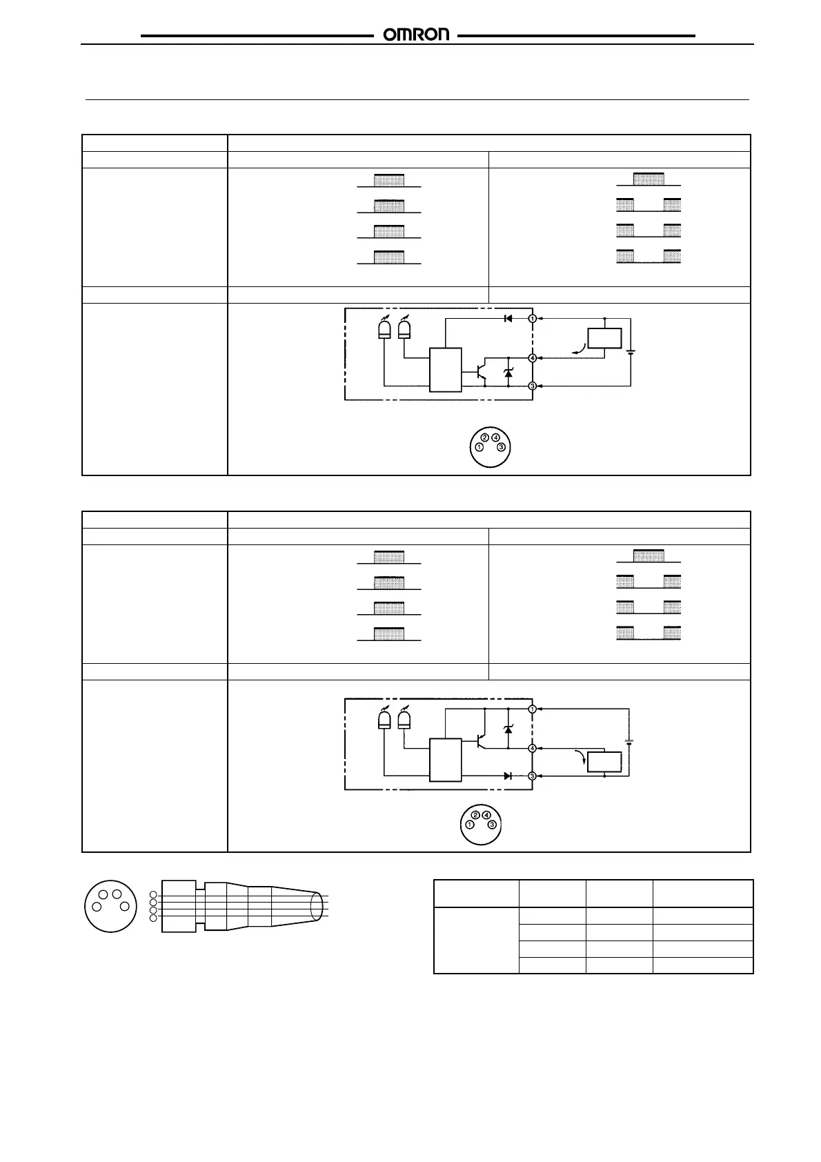
Operation
■ NPN Output
■ PNP Output
Structure of Sensor I/O Connector
Note Pin 2 is not used.
Model E3Z-B61/-B66/-B62/-B67
Output transistor status Light ON Dark ON
Timing chart
Mode selector Light ON (L/ON) Dark ON (D/ON)
Output circuit
Model E3Z-B81/-B82/-B86/-B87
Output transistor status Light ON Dark ON
Timing chart
Mode selector Light ON (L/ON) Dark ON (D/ON)
Output circuit
Incident
ON
Operation
indicator
(orange)
Output
transistor
Load
(relay)
Interrupted
OFF
ON
OFF
Operate
Reset
(Between brown and black)
Incident
ON
Operation
indicator
(orange)
Output
transistor
Load
(relay)
Interrupted
OFF
ON
OFF
Operate
Reset
(Between brown and black)
Operation
indicator
Stability
indicator
Main
circuit
Orange
Green
100 mA
max.
Load
(Relay)
Brown
Black
Blue
Control output
12 to 24 VDC
0 V
Connector Pin Arrangement
Pin 2 is open.
Incident
ON
Operation
indicator
(orange)
Output
transistor
Load
(relay)
Interrupted
OFF
ON
OFF
Operate
Reset
(Between brown and black)
Incident
ON
Operation
indicator
(orange)
Output
transistor
Load
(relay)
Interrupted
OFF
ON
OFF
Operate
Reset
(Between brown and black)
Operation
indicator
Stability
indicator
Main
circuit
Orange
Green
100 mA
max.
Load
(Relay)
Brown
Black
Blue
Control output
12 to 24 VDC
0 V
Connector Pin Arrangement
Pin 2 is open.
2
4
1
3
1
2
3
4
Brown
White
Blue
Black
Wire color
XS3F-M421-402-A
XS3F-M421-405-A
XS3F-M422-402-A
XS3F-M422-405-A
Classification Wire color Connector
pin No.
Use
DC Brown A Power supply (+V)
White B ---
Blue C Power supply (0 V)
Black D Output
 Loading...