EasyManua.ls Logo

Omron E3K User Manual

Omron E3K
1 page
Page #1 background imageLoading...
Page #1 background image
LIGHT STATUS
Green = Power On &
Aim is Stable
Red = Unit “Sees”
the Reflector
Yellow = Unit Does Not
“See” the
Reflector
Normal
Unit thinks there
is an obstruction,
aim is off or the
reflector is bad.
In Dark On Mode
If unit is in Light On Mode,
the Red & Yellow LED’s
are the OPPOSITE.
Wiring
Sensitivity
Dark Switch
OMRON E3K
Reflector Type Photo Eye
(24 to 240 VAC or VDC)
UL 325 Compliant
Instructions
Set Dark Switch to Dark ON.
Set Sensitivity near Max.
Wire Red & Black to Power.
Wire White to C1.
Wire Green to NO1.
Loosely Mount Photo Eye.
Solidly Mount Reflector, level
with the Photo Eye’s Lens.
Tip Photo Eye Up & Down, Side
to Side, until Red changes to
Yellow to determine Horizontal
& Vertical Center. Tighten.
Question and Answer IconNeed help?

Do you have a question about the Omron E3K and is the answer not in the manual?
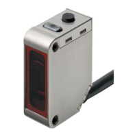
Omron E3K Specifications

General IconGeneral
Protection RatingIP67
Detection MethodRetro-reflective
Light SourceInfrared LED
Power Supply Voltage12 to 24 VDC ±10%, ripple (p-p): 10% max.
Output TypeNPN/PNP
ConnectionCable
Housing MaterialPlastic
Operating Temperature-25 to 55 °C (with no icing or condensation)

Summary

OMRON E3K Reflector Type Photo Eye

Setup Instructions

Provides essential steps for initial setup, wiring, mounting, and alignment of the OMRON E3K photo eye.

Sensitivity Adjustment

Explains how to adjust the sensitivity setting of the photo eye using the dedicated dial for optimal performance.

Dark ON/OFF Mode Switch

Details the function and operation of the Dark ON/OFF switch for selecting the operating mode.

Wiring Diagram and Connections

Illustrates the correct terminal connections for power supply and output signaling for the photo eye.

Light Status Indicators Explained

Explains the meaning of the Red and Yellow LEDs in Dark On Mode for status indication and operation.

Related product manuals