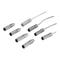
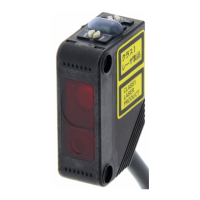
E3F3 Photoelectric Sensor 7
Precautions
If the input/output lines of the photoelectric sensor are placed in the
same conduit or duct as power lines or high-voltage lines, the photo-
electric sensor could be induced to malfunction, or even be dam-
aged, by electrical noise. Separate the wiring, or use shielded lines
as input/output lines to the photoelectric sensor.
Do not subject the photoelectric sensor to excessive shock when
mounting, in keeping with IP66 standards.
When you use the photoelectric sensor in the vicinity of an inverter
motor, be sure to connect the protective ground wire of the motor to
ground. Failure to ground the motor may result in malfunction of the
sensor.
Mounting
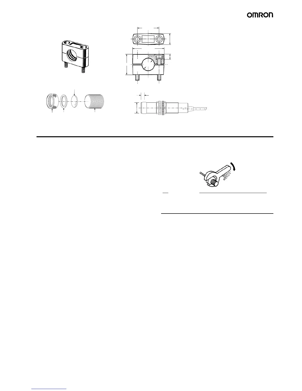
Do not exceed a torque of 20 kgf·cm (2.0 N·m) when tightening
mounting nuts.
!WARNING
The E3F3 Photoelectric sensor is not a safety component for en-
suring the safety of people as defined by EC Directives (91/386
EEC) and covered by separate European standards or by any oth-
er regulations or standards.
Y92E-B18 Mounting Bracket
E39-F31 Lens Cap
Note: Hexagonal bolt: M5 x 32
Material: plastic
32+0.2
17 max.
7
18 dia.
30
47 max.
20 dia.
4 max.
Metal rim
Gasket
E3F3
Glass plate