EasyManua.ls Logo

Omron E3Z-LR User Manual

Omron E3Z-LR
16 pages
To Next Page IconTo Next Page
Page #1 background imageLoading...
Page #1 background image
1
CSM_E3Z-LT_LR_LL_DS_E_6_8
Compact Laser Photoelectric Sensor with Built-in Amplifier
E3Z-LT/LR/LL
For the most recent information on models that have been certified for
safety standards, refer to your OMRON website.
Applications
Greatly Enhanced Beam Visibility
for Easier Optical Axis Adjustment of Sensors
Detect the sides of large tiles.
Detect chip components on tape.
Long-distance Sensing
at 300 mm (White Paper)
Reliable Detection of
Small Objects and
Narrow Gaps with the Small Spot
Count bottles.
Detect protruding straws.
A Low Black/White Error for
Applications with Mixed Colors
Compact and Reliable
Laser Photoelectric Sensor
Safety and reliability with laser class 1 (JIS and IEC).
Product lineup includes models with distance setting without
influence of color.
Maximum ambient operating temperature of 55°C and water-
proof construction in E3Z class.
Be sure to read Safety Precautions on
page 9.
Question and Answer IconNeed help?

Do you have a question about the Omron E3Z-LR and is the answer not in the manual?

Omron E3Z-LR Specifications

General IconGeneral
ModelE3Z-LR
TypePhotoelectric Sensor
Sensing MethodThrough-beam
Light SourceRed LED
Response Time1 ms
Operating Temperature-25 to 55 °C
Degree of ProtectionIP67
Housing MaterialPlastic
Protection RatingIP67
Supply Voltage12-24V DC
Protection CircuitReverse polarity
Connection TypeCable

Summary

Compact and Reliable Laser Photoelectric Sensor

Applications

Showcases practical uses like detecting tiles, counting bottles, and identifying small components.

Ordering Information

Sensor Models and Specifications

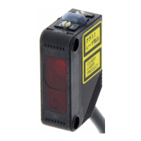
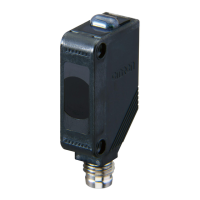
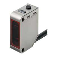
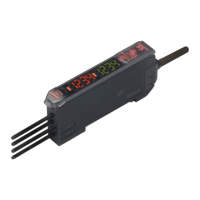
Details available sensor models based on sensing method, connection, and output type.

Required Accessories

Lists necessary accessories like slits and reflectors for specific sensor types.

Mounting Brackets

Bracket Types and Usage

Describes various mounting brackets available for securing the sensor.

Sensor I/O Connectors

Connector Types and Specifications

Details M8 4-pin connectors for sensor wiring and connections.

Ratings and Specifications

Performance Characteristics by Sensing Method

Provides detailed technical specifications for sensing methods, response, and output.

Engineering Data (Reference Value)

Parallel Operating Range

Visualizes sensing ranges for different models and conditions.

Operating Range at a Set Distance

Shows sensing range variations based on distance settings for BGS models.

Detailed Engineering Performance Data

Sensing Distance vs. Sensing Object Material

Analyzes sensing distance variations based on object material and set distance.

Emission Spot Diameter vs. Distance

Shows how emission spot diameter changes with sensing distance.

Hysteresis vs. Distance

Illustrates hysteresis variations based on distance for BGS models.

Inclination Characteristics

Details sensitivity changes with vertical and horizontal inclination angles.

I/O Circuit Diagrams

NPN Output Circuitry

Illustrates internal wiring and operation logic for NPN output models.

PNP Output Circuitry

Illustrates internal wiring and operation logic for PNP output models.

Plugs (Sensor I/O Connectors)

M8 Connector Pin Assignments and Wire Colors

Shows wire color mapping and pin configuration for M8 connectors.

Nomenclature

Sensor Component Identification

Identifies key components like indicators and adjusters on the sensor.

Safety Precautions

Precautions for Safe Use

Covers warnings, cautions, and best practices for safe operation.

Precautions for Correct Use

Provides guidelines on appropriate usage environments and design considerations.

Mounting Direction for Distance-settable Models

Mounting Alignment and Stability

Provides specific advice on mounting orientation and alignment for BGS models.

Inspection and Maintenance

Cleaning and Stability Indicator Checks

Outlines maintenance tasks like cleaning and checking stability indicators.

Through-beam Sensor Dimensions

Pre-wired and Standard Connector Models

Displays detailed physical measurements for Through-beam sensor models.

Retro-reflective Sensor Dimensions

Pre-wired and Standard Connector Models

Shows physical dimensions for Retro-reflective sensor models.

BGS Sensor Dimensions

Pre-wired and Standard Connector Models

Provides physical measurements for Background Suppression (BGS) sensor models.

Accessories (Order Separately)

Slits and Reflectors Specifications

Details the specifications and materials for optional accessories like slits and reflectors.

Terms and Conditions Agreement

Warranty and Liability Limitations

Outlines Omron's warranty, disclaimers, and limitations of liability.