E3Z-LT/LR/LL
7
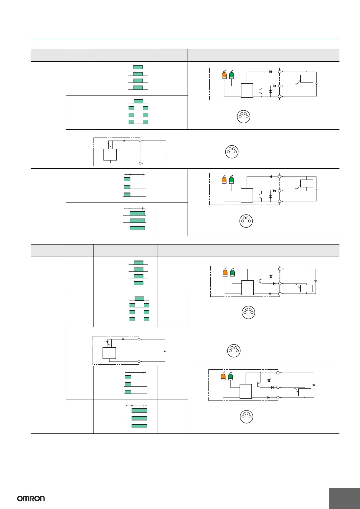
I/O Circuit Diagrams
NPN Output
PNP Output
* Models numbers for Through-beam Sensors (E3Z-LT@@) are for sets that include both the Emitter and Receiver.
The model number of the Emitter is expressed by adding "-L" to the set model number (example: E3Z-LT61-L 2M), the model number of the Receiver, by adding "-D"
(example: E3Z-LT61-D 2M.) Refer to Ordering Information to confirm model numbers for Emitter and Receivers.
Model
Operation
mode
Timing charts
Operation
selector
Output circuit
E3Z-LT61 *
E3Z-LT66 *
E3Z-LR61
E3Z-LR66
Light-ON
L side
(LIGHT ON)
Dark-ON
D side
(DARK ON)
E3Z-LL61
E3Z-LL66
E3Z-LL63
E3Z-LL68
Light-ON
L side
(LIGHT ON)
Dark-ON
D side
(DARK ON)
Light incident
Light interrupted
ON
OFF
ON
OFF
Operate
Reset
Operation indicator
(orange)
(Between brown A and black D leads)
Output transistor
Load
(e.g., relay)
4
3
1
100 mA
max.
0 V
Z
D
1
2
4
3
12 to 24 VDC
Through-beam Receivers, Retro-reflective Models
Pin 2 is not used.
Brown
Black
(Control
output)
Blue
Operation
indicator
Stability
indicator
(Green)
(Orange)
Load
(Relay)
Photo-
electric
Sensor
Main
Circuit
M8 4-pin Connector
Pin Arrangement
Light incident
Light interrupted
ON
OFF
ON
OFF
Operate
Reset
Operation indicator
(orange)
(Between brown A and black D leads)
Output transistor
Load
(e.g., relay)
3
1
1
2
4
3
12 to 24 VDC
Through-beam Emitter
Power
indicator
(orange)
Pins 2 and 4
are not used.
Brown
Blue
Photo-
electric
Sensor Main
Circuit
M8 4-pin Connector
Pin Arrangement
ON
OFF
ON
OFF
Operate
Reset
NEAR FAR
Operation
indicator
(orange)
Output
transistor
Load
(e.g., relay)
(Between brown A and black D leads)
4
3
1
1
2
4
3
100 mA
max.
0 V
Z
D
12 to 24 VDC
Pin 2 is not used.
Brown
Black
(Control
output)
Blue
Operation
indicator
Stability
indicator
(Green)
(Orange)
Load
(Relay)
Photo-
electric
Sensor
Main
Circuit
M8 4-pin Connector
Pin Arrangement
ON
OFF
ON
OFF
Operate
Reset
NEAR FAR
Operation
indicator
(orange)
Output
transistor
Load
(e.g., relay)
(Between brown A and black D leads)
Model
Operation
mode
Timing charts
Operation
selector
Output circuit
E3Z-LT81 *
E3Z-LT86 *
E3Z-LR81
E3Z-LR86
Light-ON
L side
(LIGHT ON)
Dark-ON
D side
(DARK ON)
E3Z-LL81
E3Z-LL86
E3Z-LL83
E3Z-LL88
Light-ON
L side
(LIGHT ON)
Dark-ON
D side
(DARK ON)
Light incident
Light interrupted
ON
OFF
ON
OFF
Operate
Reset
Operation indicator
(orange)
(Between blue C and black D leads)
Output transistor
Load
(e.g., relay)
4
1
3
1
2
4
3
Through-beam Receivers, Retro-reflective Models
100 mA
max.
0 V
Z
D
12 to 24 VDC
Pin 2 is not used.
Brown
Black
(Control
output)
Blue
Operation
indicator
Stability
indicator
(Green)
(Orange)
Load
(Relay)
Photo-
electric
Sensor
Main
Circuit
M8 4-pin Connector
Pin Arrangement
Light incident
Light interrupted
ON
OFF
ON
OFF
Operate
Reset
Operation indicator
(orange)
(Between blue C and black D leads)
Output transistor
Load
(e.g., relay)
3
1
1
2
4
3
12 to 24 VDC
Through-beam Emitter
Power
indicator
(orange)
Pins 2 and 4 are not used.
Brown
Blue
Photo-
electric
Sensor Main
Circuit
M8 4-pin Connector
Pin Arrangement
ON
OFF
ON
OFF
Operate
Reset
NEAR
FAR
Operation
indicator
(orange)
Output
transistor
Load
(e.g., relay)
(Between blue C and black D leads)
1
2
4
3
4
1
3
100 mA
max.
0 V
Z
D
12 to 24 VDC
Pin 2 is not used.
Brown
Black
(Control
output)
Operation
indicator
Stability
indicator
(Green)
(Orange)
Load
(Relay)
Photo-
electric
Sensor
Main
Circuit
M8 4-pin Connector
Pin Arrangement
Blue
ON
OFF
ON
OFF
Operate
Reset
NEAR FAR
Operation
indicator
(orange)
Output
transistor
Load
(e.g., relay)
(Between blue C and black D leads)