E3Z-LT/LR/LL
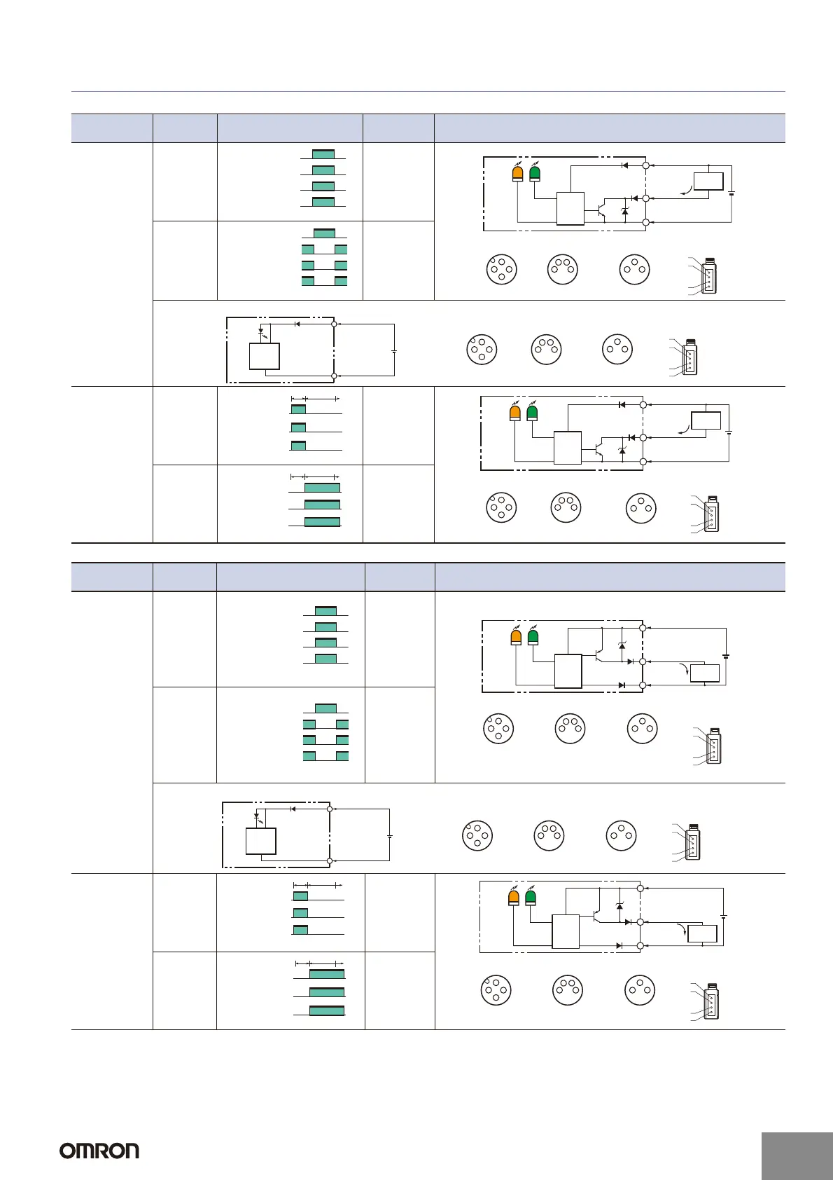
I/O Circuit Diagrams
NPN Output
PNP Output
Model
Operation
mode
Timing charts
Operation
selector
Output circuit
E3Z-LT61
E3Z-LT66
E3Z-LR61
E3Z-LR66
Light-ON
L side
(LIGHT ON)
Dark-ON
D side
(DARK ON)
E3Z-LL61
E3Z-LL66
E3Z-LL63
E3Z-LL68
Light-ON
L side
(LIGHT ON)
Dark-ON
D side
(DARK ON)
Light incident
Light interrupted
ON
OFF
ON
OFF
Operate
Reset
Operation indicator
(orange)
(Between brown and black leads)
Output transistor
Load
(e.g., relay)
4
3
1
100 mA
max.
0 V
Z
D
1
2
3
4
3
1
2
4
1
2
4
3
12 to 24 VDC
Through-beam Receivers, Retro-reflective Models
e-CON Connector
Pin Arrangement
Pin 2 is not used.
Press fit
Brown
Black
(Control
output)
Blue
Operation
indicator
Stability
indicator
(Green)
(Orange)
Load
(Relay)
Photo-
electric
Sensor
Main
Circuit
M12 Connector
Pin Arrangement
M8 4-pin Connector
Pin Arrangement
4
1
3
M8 3-pin Connector
Pin Arrangement
Light incident
Light interrupted
ON
OFF
ON
OFF
Operate
Reset
Operation indicator
(orange)
(Between brown and black leads)
Output transistor
Load
(e.g., relay)
3
1
1
2
3
4
3
1
2
4
1
2
4
3
12 to 24 VDC
Through-beam Emitter
Power
indicator
(orange)
e-CON Connector
Pin Arrangement
Press fit
Pins 2 and 4
are not used.
Brown
Blue
Photo-elec-
tric Sensor
Main
Circuit
M12 Connector
Pin Arrangement
M8 4-pin Connector
Pin Arrangement
4
1
3
M8 3-pin Connector
Pin Arrangement
ON
OFF
ON
OFF
Operate
Reset
NEAR FAR
Operation
indicator
(orange)
Output
transistor
Load
(e.g., relay)
(Between brown and black leads)
4
3
1
1
2
3
4
3
1
2
4
1
2
4
3
100 mA
max.
0 V
Z
D
12 to 24 VDC
e-CON Connector
Pin Arrangement
Pin 2 is not used.
Press fit
Brown
Black
(Control
output)
Blue
Operation
indicator
Stability
indicator
(Green)
(Orange)
Load
(Relay)
Photo-
electric
Sensor
Main
Circuit
M12 Connector
Pin Arrangement
M8 4-pin Connector
Pin Arrangement
4
1
3
M8 3-pin Connector
Pin Arrangement
ON
OFF
ON
OFF
Operate
Reset
NEAR FAR
Operation
indicator
(orange)
Output
transistor
Load
(e.g., relay)
(Between brown and black leads)
Model
Operation
mode
Timing charts
Operation
selector
Output circuit
E3Z-LT81
E3Z-LT86
E3Z-LR81
E3Z-LR86
Light-ON
L side
(LIGHT ON)
Dark-ON
D side
(DARK ON)
E3Z-LL81
E3Z-LL86
E3Z-LL83
E3Z-LL88
Light-ON
L side
(LIGHT ON)
Dark-ON
D side
(DARK ON)
Light incident
Light interrupted
ON
OFF
ON
OFF
Operate
Reset
Operation indicator
(orange)
(Between blue and black leads)
Output transistor
Load
(e.g., relay)
4
1
3
1
2
3
4
4
1
3
3
1
2
4
1
2
4
3
Through-beam Receivers, Retro-reflective Models
100 mA
max.
0 V
Z
D
12 to 24 VDC
e-CON Connector
Pin Arrangement
Pin 2 is not used.
Press fit
Brown
Black
(Control
output)
Blue
Operation
indicator
Stability
indicator
(Green)
(Orange)
Load
(Relay)
Photo-
electric
Sensor
Main
Circuit
M12 Connector
Pin Arrangement
M8 4-pin Connector
Pin Arrangement
M8 3-pin Connector
Pin Arrangement
Light incident
Light interrupted
ON
OFF
ON
OFF
Operate
Reset
Operation indicator
(orange)
(Between blue and black leads)
Output transistor
Load
(e.g., relay)
3
1
1
2
3
4
4
1
3
3
1
2
4
1
2
4
3
12 to 24 VDC
Through-beam Emitter
Power
indicator
(orange)
Pins 2 and 4 are not used.
Brown
Blue
e-CON Connector
Pin Arrangement
Press fit
Photo-elec-
tric Sensor
Main
Circuit
M12 Connector
Pin Arrangement
M8 4-pin Connector
Pin Arrangement
M8 3-pin Connector
Pin Arrangement
ON
OFF
ON
OFF
Operate
Reset
NEAR
FAR
Operation
indicator
(orange)
Output
transistor
Load
(e.g., relay)
(Between blue and black leads)
1
2
3
4
4
1
3
3
1
2
4
1
2
4
3
4
1
3
100 mA
max.
0 V
Z
D
12 to 24 VDC
e-CON Connector
Pin Arrangement
Pin 2 is not used.
Press fit
Brown
Black
(Control
output)
Operation
indicator
Stability
indicator
(Green)
(Orange)
Load
(Relay)
Photo-
electric
Sensor
Main
Circuit
M12 Connector
Pin Arrangement
M8 4-pin Connector
Pin Arrangement
M8 3-pin Connector
Pin Arrangement
Blue
ON
OFF
ON
OFF
Operate
Reset
NEAR FAR
Operation
indicator
(orange)
Output
transistor
Load
(e.g., relay)
(Between blue and black leads)
http://www.ia.omron.com/
7
(c)Copyright OMRON Corporation 2007 All Rights Reserved.
 Loading...