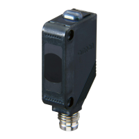
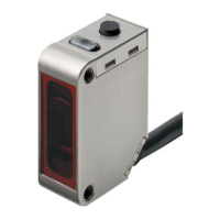
E3Z-LT/LR/LL
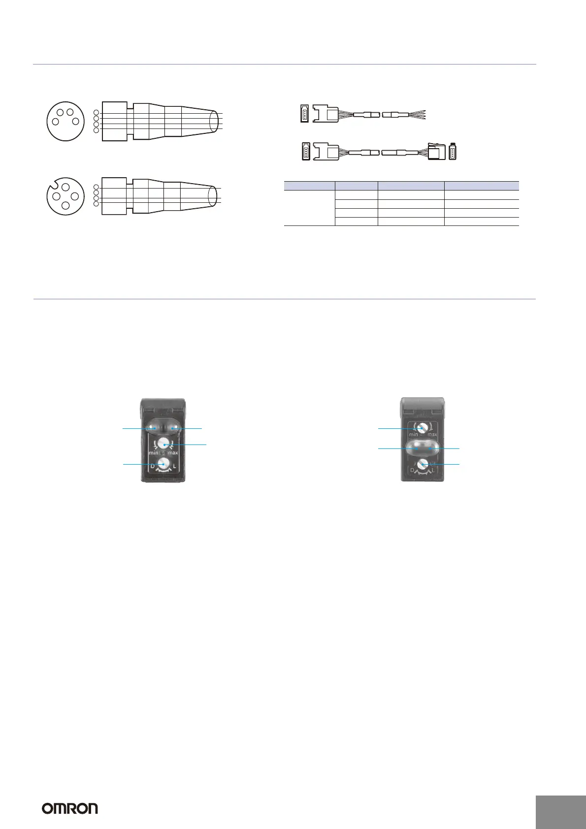
Plugs (Sensor I/O Connectors)
Nomenclature
2
4
13
1
2
3
4
Pin No.
XS2F-D421-DC0-A
XS2F-D421-GC0-A
XS2F-D422-DC0-A
XS2F-D422-GC0-A
Brow
Blue
Black
Wire colo
1234
1234
4
3
1
2
E39-ECON@M
E39-ECONW@M
8 4-pin Connectors
e-CON Connector
2
4
1
3
1
2
3
4
XS3F-M421-402-A
XS3F-M421-405-A
XS3F-M422-402-A
XS3F-M422-405-A
Brown
White
Blue
Black
Wire color
12 Connectors
Å@
Note: 1. Pin 2 is not used.
2. The above M8 and M12 Connectors made by OMRON are IP67.
Classification Wire color Connector pin No. Application
DC
Brown 1 Power supply (+V)
White 2 ---
Blue 3 Power supply (0 V)
Black 4 Output
Distance adjuster
(5-turn endless)
Stability indicator
(green)
Operation selector
Operation indicator
(orange)
Sensitivity adjuster
Stability indicator
(green)
Operation indicato
(orange)
Mode selector
switch
Sensors with Sensitivity Adjustment and
Mode Selector Switch
Through-beam Models
E3Z-LT@@ (Receiver)
Retro-reflective Models
E3Z-LR@@
Distance-settable Sensor
BGS Models
E3Z-LL@@
http://www.ia.omron.com/
8
(c)Copyright OMRON Corporation 2007 All Rights Reserved.