E5CC-800/E5CC-B-800/E5CC-U-800
13
Isolation/Insulation Block Diagrams
• E5CC-800
Models with 2 Auxiliary Outputs
• E5CC-B-800
Models with 2 Auxiliary Outputs
• E5CC-U-800
Models with 2 Auxiliary Outputs
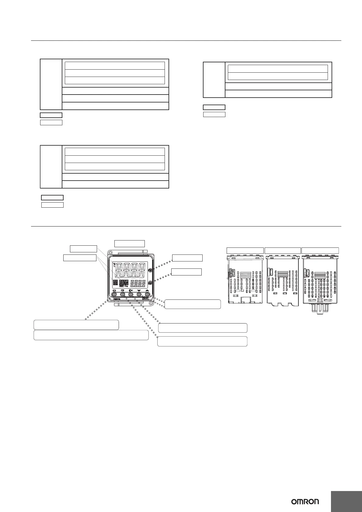
Nomenclature
Communications and event inputs
Sensor input and CT input
Voltage output (for driving SSR) and linear current output
Relay output
Auxiliary output 1
Power
supply
Auxiliary output 2
: Reinforced insulation
: Functional isolation
Sensor input and CT input
Communications
Voltage output (for driving SSR) and linear current output
Relay output
Auxiliary outputs 1, 2
: Reinforced insulation
: Functional isolation
Power
supply
Sensor input
Voltage output (for driving SSR)
Relay output
Auxiliary outputs 1 and 2
: Reinforced insulation
: Functional isolation
Power
supply
Press O Key once to go to Adjustment Level.
Press O Key for at least 3 seconds to go to Initial Setting Level.
Use the M Key to change to another parameter.
Operation indicators
No. 1 display
No. 2 display
Temperature unit
Use S Key to change the digit (default setting).
Use the U D Keys to set the
parameter.
Front panel
PV or specified parameter
SP or specified parameter value
Top View of E5CC-800
Top View of E5CC-U-800
Top View of E5CC-B-800
E5CC-800
E5CC-B-800
E5CC-U-800

 Loading...


