E5EC-800/E5EC-B-800/E5AC-800
28
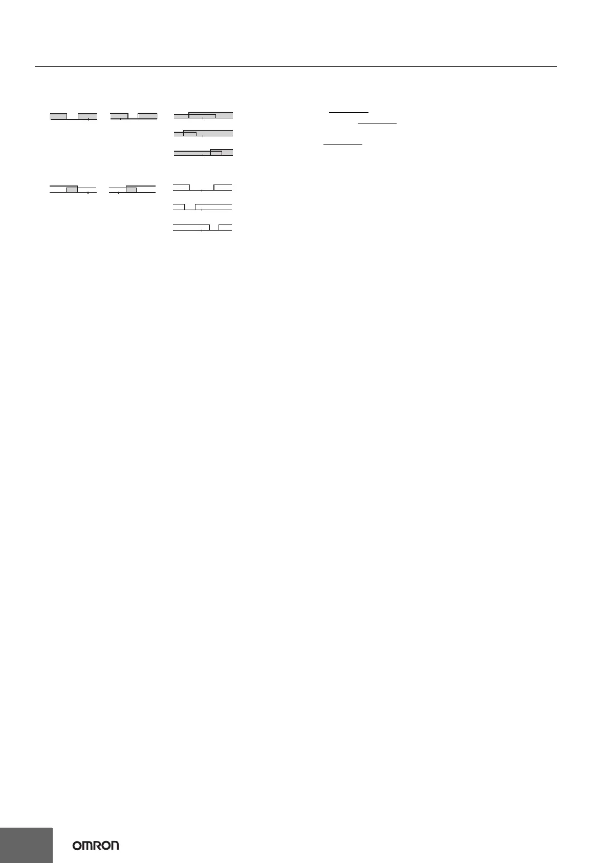
*1 With set values 1, 4 and 5, the upper and lower limit values can be set
independently for each alarm type, and are expressed as “L” and “H.”
*2. Set value: 1, Upper- and lower-limit alarm
*3. Set value: 4, Upper- and lower-limit range
*4. Set value: 5, Upper- and lower-limit with standby sequence
For Upper- and Lower-Limit Alarm Described Above *2
• Case 1 and 2
Always OFF
when the upper-limit and lower-limit hysteresis overlaps.
• Case 3: Always OFF
*5. Set value: 5, Upper- and lower-limit with standby sequence
Always OFF
when the upper-limit and lower-limit hysteresis overlaps.
*6. Refer to the E5@C Digital Temperature Controllers User's Manual (Cat. No.
H174) for information on the operation of the standby sequence.
*7. Refer to the E5@C Digital Temperature Controllers User's Manual (Cat. No.
H174) for information on the PV change rate alarm. This setting cannot be
used with a position-proportional model.
*8. Refer to the E5@C Digital Temperature Controllers User's Manual (Cat. No.
H174) for information on the PV change rate alarm.
*9. When heating/cooling control is performed, the MV absolute upper limit
alarm functions only for the heating operation and the MV absolute lower
limit alarm functions only for the cooling operation.
LHSP
Case 1
LHSP
Case 2
LHSP
LHSP
LHSP
Case 3 (Always ON)
H<0, L<0
H<0, L>0
|H| ≥ |L|
H>0, L<0
|H| ≤ |L|
H<0, L>0
|H| < |L|
H>0, L<0
|H| > |L|
LHSP
Case 1
LHSP
Case 2
LHSP
L
L
HSP
HSP
Case 3 (Always OFF)
H<0, L>0
|H| < |L|
H>0, L<0
|H| > |L|
H<0, L<0
H<0, L>0
|H| ≥ |L|
H>0, L<0
|H| ≤ |L|
 Loading...