E5EC-800/E5EC-B-800/E5AC-800
32
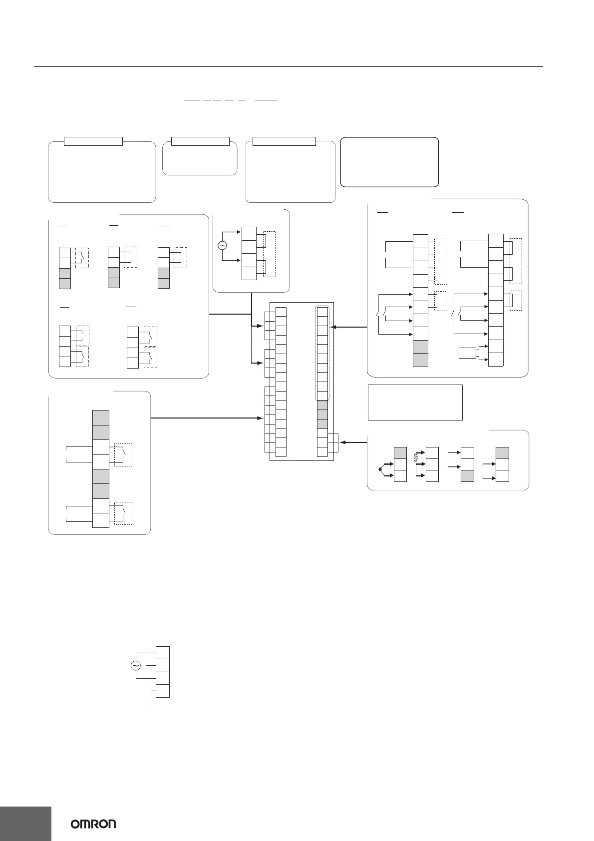
E5EC-B-800 (Push-In Plus Terminal Blocks)
27
28
26
17
29
30
31
32
19
20
18
21
22
23
24
25
1
2
3
4
32
Pt
A
B
B
+
-
m
-
+
31
30
32
31
30
32
31
30
32
31
30
V
-
V
+
TC
I
11
12
9
10
2
1
7
8
5
6
3
4
13
14
15
16
*
*
↑
Terminal type
E5EC-@@
2
A B M - 8@@
(1)
(2)
(3)
(4)
(5) (6)
The E5EC-B-800 is set for a K-type
thermocouple (input type = 5) by
default. An input error (s.err) will
occur if the input type setting does
not agree with the temperature
sensor. Check the input type.
Relay output
250 VAC, 5 A (resistive load)
Voltage output
(for driving SSR)
12 VDC, 40 mA
21 mA if there are two control
outputs
Control output 1
Relay output
250 VAC, 5 A
(resistive load)
Control output 2
Auxiliary outputs 1, 2
Relay output
Model with 2 auxiliary
outputs: 250 VAC, 3 A
(resistive load)
(1) Control output
100 to 240 VAC
(3) Input Power Supply
Auxiliary outputs 1, 2
(2) Auxiliary Outputs
9
10
11
12
13
14
15
16
Auxiliary output 1
Auxiliary output 2
(5) Sensor (Temperature/Analog) Input
(6) Options
Use no-voltage inputs for the
event inputs.
The polarity for non-contact
inputs is given in parentheses.
808
18
17
19
20
21
22
23
25
26
24
CT1
EV2
EV1
B(+)
A(-)
RS-485
*
*
*
Communications, 2 event
inputs, and 1 CT input
(-)
(-)
804
18
17
19
20
21
22
23
25
26
24
EV2
EV1
B(+)
A(-)
RS-485
*
*
*
Communications, 2 event
inputs
(-)
(-)
Models with
1 Relay Output
Models with Voltage Output (for
Driving SSR) and Relay Output
Models with 2
Relay Outputs
RX
QR
RR
+
-
5
6
7
8
5
6
7
8
5
6
7
8
R
R
R
R
Q
Models with 1 Linear
current output
CX
+
-
5
6
7
8
C
OUT1
OUT1
OUT1
OUT2
OUT1
OUT2
Models with 1
Voltage Output
(for Driving SSR)
QX
+
-
5
6
7
8
Q
OUT1
Note: 1. The application of the terminals depends on the model.
2. Do not wire the terminals that are shown with a gray background.
3. When complying with EMC standards, the cable that connects the sensor must be 30 m or less. If the cable length exceeds 30 m,
compliance with EMC standards will not be possible.
4. Refer to Wiring Precautions for E5
@
C-B (Controllers with Push-In Plus Terminal Blocks) on page 65 for wire specifications and wiring
methods.
5. Common terminals are indicated with asterisks (*). You can use the input power supply and communications common terminals for
crossover wiring. Do not exceed the maximum number of Temperature Controllers given below if you use crossover wiring for the
input power supply.
100 to 240 VAC Controllers: 16 max.
6. Due to UL Listing requirements, use the E54-CT1L or E54-CT3L Current Transformer with the factory wiring (internal wiring).
Use a UL category XOBA or XOBA7 current transformer that is UL Listed for field wiring (external wiring) and not the factory wiring
(internal wiring).
1
2
3
4
To another E5@C
Wiring Example:
 Loading...