Digital Controller E5CK I-69
Temperature
Controller
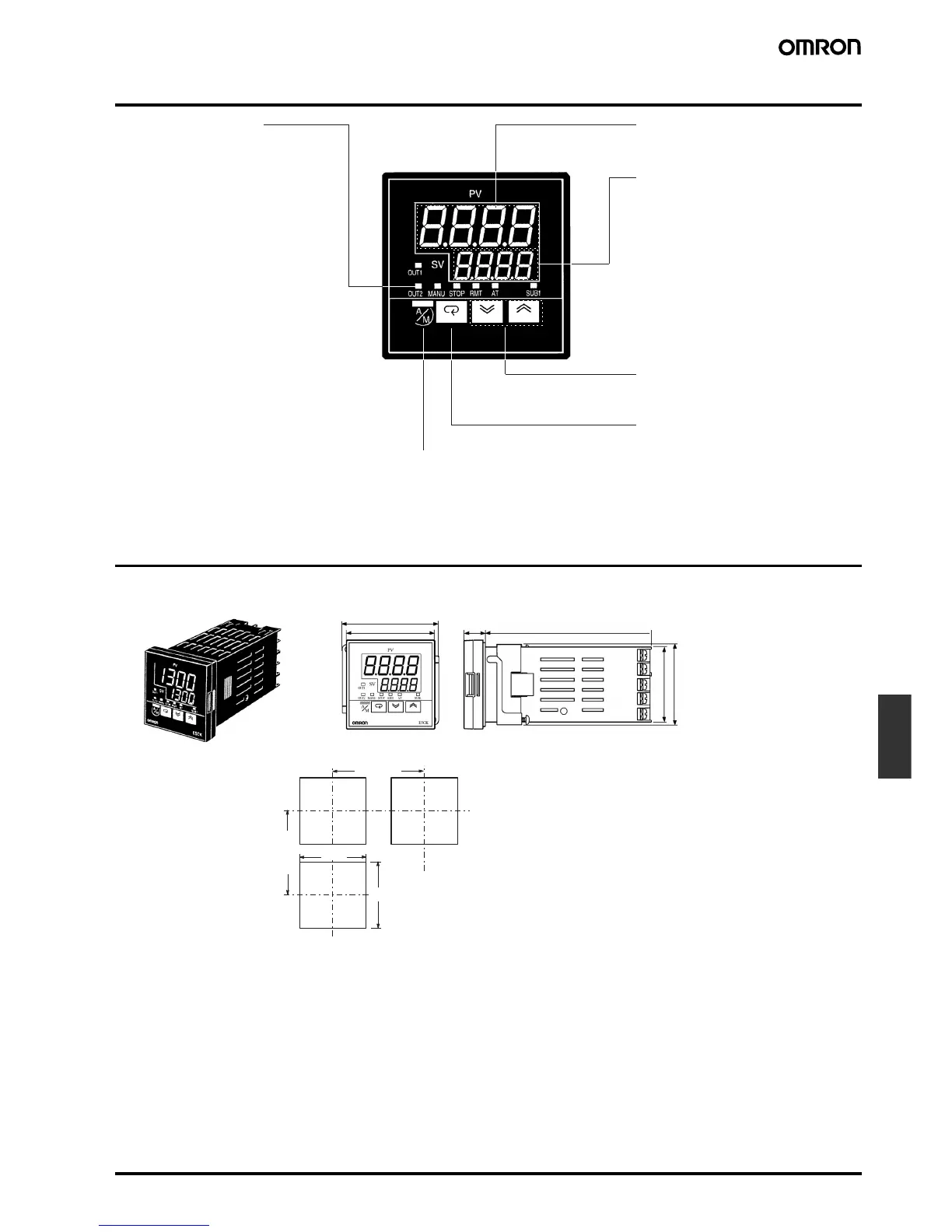
Nomenclature
Dimensions
Note: All units are in millimeters unless otherwise indicated.
Operation Indicators
A/M Key
No. 1 Display
No. 2 Display
Up Key/Down Key
Display Key
•
OUT1
Lights when the pulse output
function assigned to control
output 1 turns ON.
•
OUT2
Lights when the pulse output
function assigned to control
output 2 turns ON.
•
SUB1
Lights when the output func-
tion assigned to auxiliary
output 1 turns ON.
•
MANU
Lights when the manual op-
eration mode.
•
STOP
Lights during operation has
stopped.
•
RMT
Lights during remote opera-
tion.
•
AT
Flashes during auto-tuning.
Press to select the auto operation or
manual operation.
Press for less than 1 s to shift the
display to the next parameter. When
this key is pressed for 1 s or more,
the menu screen will be displayed in
any case.
Press to increase or decrease the
value on the No.2 display.
Displays the set point, set point dur-
ing SP ramp, manipulated variable,
or parameter settings.
Displays the process value or pa-
rameter symbols.
58
53 x 53
13 100
44.8 x 44.8
48
45
+0.6
0
45
+0.6
0
E5CK
Panel Cutouts
65 min.
60 min.
Note: 1. Recommended panel thickness is 1 to 5 mm.
2. Maintain the specified vertical and horizontal mount-
ing space between each Unit. Units must not be
closely mounted vertically or horizontally.