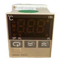
E5EC/E5EC-B/E5AC
41
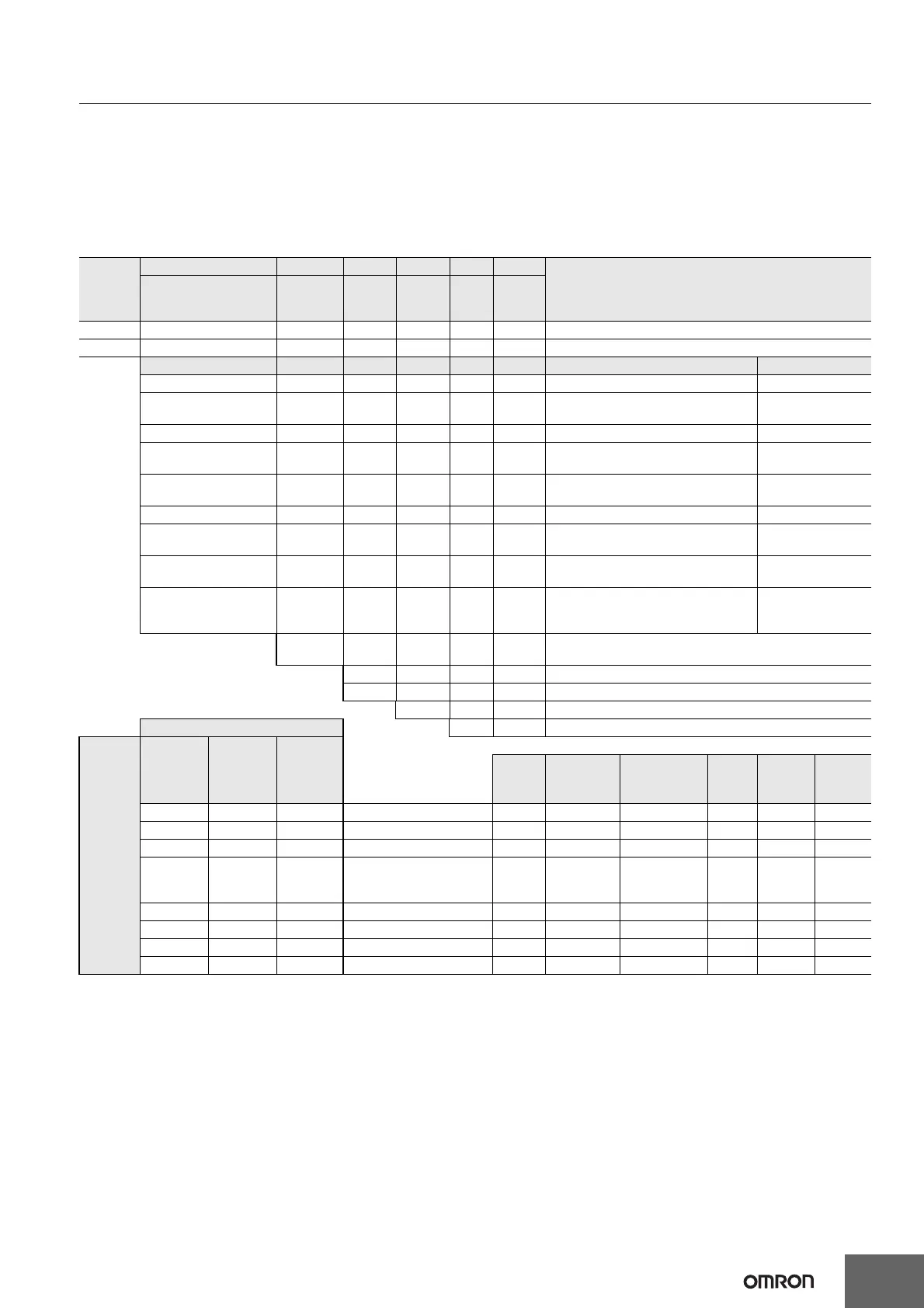
Model Number Legend and Standard Models
Model Number Legend
Models with Screw Terminal Blocks
E5EC-@@ 4 @ 5M-@@@ (Example: E5EC-RX4A5M-000)
−− −−− −
−−−
ABCDEF
E5AC-@@ 4 @ 5M-@@@ (Example: E5AC-RX4A5M-000)
−− −−− −
−−−
ABCDEF
*1. The options that can be selected depend on the type of control output.
*2. The control output cannot be used as a transfer output.
*3. A model with four auxiliary outputs must be selected.
Note: Draw-out-type models of the E5EC and E5AC are available. Ask your OMRON representative for details.
Heating and Cooling Control
Using Heating and Cooling Control
A Control Output Assignment
If there is no control output 2, an auxiliary output is used as the cooling control output.
If there is a control output 2, the two control outputs are used for heating and cooling.
(It does not matter which output is used for heating and which output is used for cooling.)
B Control
If PID control is used, you can set PID control separately for heating and cooling.
This allows you to handle control systems with different heating and cooling response characteristics.
Model
A B C D E F
Meaning
Control outputs
1 and 2
No. of
auxiliary
outputs
Power
supply
voltage
Terminal
type
Input
type
Options
E5EC 48 × 96 mm
E5AC 96 × 96 mm
Control output 1 Control output 2
RX Relay output None
QX
Voltage output
(for driving SSR)
None
*2 CX Linear current output None
QQ
Voltage output
(for driving SSR)
Voltage output
(for driving SSR)
QR
Voltage output
(for driving SSR)
Relay output
RR Relay output Relay output
*2 CC Linear current output
Linear current
output
*2 CQ Linear current output
Voltage output
(for driving SSR)
PR Position-proportional relay output
Position-
proportional relay
output
*3 4
4 (auxiliary outputs 1 and 2 with same common and
auxiliary outputs 3 and 4 with same common)
A 100 to 240 VAC
D 24 VAC/DC
5 Screw terminal blocks (with cover)
Control outputs 1 and 2 M Universal input
Option
selection
conditions
*1
For RX,
QX, QQ,
QR, RR, or
CQ
For CX or
CC
For PR
HB alarm
and
HS alarm
Communications
Event
inputs
Remote
SP Input
Transfer
output
Selectable Selectable Selectable 000 --- --- --- --- ---
Selectable Selectable 004 --- RS-485 2 --- ---
Selectable 005 --- --- 4 --- ---
Selectable 009
2
(for 3-phase
heaters)
RS-485 2 --- ---
Selectable 010 1 --- 4 --- ---
Selectable 011 1 --- 6 Provided. Provided.
Selectable 013 --- --- 6 Provided. Provided.
Selectable Selectable 014 --- RS-485 4 Provided. Provided.