EasyManua.ls Logo

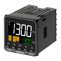
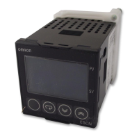
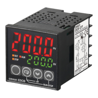
Omron E5CZ User Manual

Omron E5CZ
208 pages
To Next Page IconTo Next Page
Page #1 background imageLoading...
Page #1 background image
E5CZ
E5CZ
E5CZ
E5CZ-U
User's Manual
E5CZ-U
E5CZ-U
E5AZ
E5AZ
E5AZ
E5EZ
E5EZ
E5EZ
with 11-segment Display
Black
E5CZ/CZ-U/AZ/EZ Digital Temperature Controller
User's Manual
H207-E1-01
Digital Temperature Controller
Cat. No. H207-E1-01
OMRON Industrial Automation Global:www.ia.omron.com Cat. No. H207-E1-01
OMRON Corporation
Industrial Automation Company
Control Devices Division H.Q.
Analog Controller Division
Shiokoji Horikawa, Shimogyo-ku,
Kyoto, 600-8530 Japan
Tel: (81) 75-344-7080/Fax: (81) 75-344-7149
2-2-1 Nishikusalsu, Kusatsu-shi,
Shiga, 525-0035 Japan
Tel: (81) 77-565-5216/Fax: (81) 77-565-5568
Regional Headquarters
OMRON EUROPE B.V.
Wegalaan 67-69-2132 JD Hoofddorp
The Netherlands
Tel: (31) 2356-81-300/Fax: (31) 2356-81-388
OMRON ELECTRONICS LLC
One Commerce Drive Schaumburg,
IL 60173-5302 U.S.A.
Tel: (1) 847-843-7900/Fax: (1) 847-843-7787
OMRON ASIA PACIFIC PTE. LTD.
No.438A Alexandra Road # 05-05/08 (Lobby 2),
Alexandra Technopark, Singapore 119967
Tel: (65)6835-3011/Fax: (65) 6835-2711
OMRON (CHINA) CO., LTD
Room 2211, Bank of China Tower,
200 Yin Cheng Zhong Road ,
Pu Dong New Area, Shanghai, 200120, China
Tel: (86) 21-5037-2222/Fax: (86) 21-5037-2200
Authorized Distributor:
OMRON Corporation 2008 All Rights Reserved
In the interest of product improvement,
specitications are subject to change without notice.
C
Printed in China
0908
Table of Contents

Other manuals for Omron E5CZ

Questions and Answers:

Omron E5CZ Specifications

General IconGeneral
Display Type7-segment digital display
Dimensions48 x 48 x 78 mm
Number of Control Outputs1
Ambient Operating Temperature-10 to 55°C
Control MethodPID control, ON/OFF control
Input TypeThermocouple, RTD
Supply Voltage100 to 240 VAC
Output TypeRelay, Voltage, Current
Alarm Output1 or 2 (depending on model)
Setting Resolution0.1 or 1 (depending on input type)
Protection RatingIP20
Ambient Operating Humidity25% to 85% RH (non-condensing)

Summary

Preface

Visual Aids

Explains visual aids used in the manual for locating information, such as notes and numbered lists.

Disclaimers

Safety Precautions

Definition of Precautionary Information

Defines the notation used for safety precautions in the manual to ensure safe usage of the product.

Symbols

Lists symbols used for safety precautions, including general caution, electrical shock caution, and general prohibition.

Precautions for Safe Use

SECTION 1 Introduction

1-1 Names of Parts

Identifies and labels the various parts of the E5CZ/CZ-U and E5AZ controllers' front panels.

1-2 I/O Configuration and Main Functions

Describes the I/O configuration and main functions of the E5CZ, E5CZ-U, E5AZ, and E5EZ controllers.

1-3 Setting Level Configuration and Key Operations

Explains the seven setting levels and how to navigate between them using front panel keys.

1-4 Communications Function

Details the communications function, enabling parameter checking and setting from a host computer.

SECTION 2 Preparations

2-1 Installation

Provides guidance on the physical installation of the E5CZ and E5CZ-U controllers, including dimensions and mounting.

2-2 Wiring Terminals

Details the terminal arrangements and precautions for wiring the E5CZ, E5CZ-U, E5AZ, and E5EZ controllers.

2-3 Using the Support Software Port

Explains how to connect a personal computer to the controller for support software using a USB-Serial Conversion Cable.

SECTION 3 Basic Operation

3-1 Initial Setting Examples

Provides two typical examples of initial hardware setup, including sensor input type and alarm settings.

3-2 Setting the Input Type

Details how to set the input type that matches the sensor used, supporting various input types like thermocouple and analog.

3-3 Selecting the Temperature Unit

Explains how to select the temperature unit (°C or °F) in the initial setting level.

3-4 Selecting PID Control or ON/OFF Control

Describes the selection between 2-PID control and ON/OFF control via the 'PID ON/OFF' parameter.

3-5 Setting Output Specifications

Covers setting output periods, direct/reverse operation, and function assignments for control and alarm outputs.

3-6 Setting the Set Point (SP)

Explains how to change the set point (SP) and use the Multi-SP function for multiple set points.

3-7 Using ON/OFF Control

Details the ON/OFF control method, including hysteresis and three-position control settings.

3-8 Determining PID Constants (AT, ST, Manual Setup)

Explains how to determine PID constants using auto-tuning (AT), self-tuning (ST), or manual setup.

3-9 Alarm Outputs

Describes alarm types, alarm values, and alarm output operations based on various settings.

3-10 Using HB and HS Alarms

Covers heater burnout (HB) and HS alarm operations, installation of CTs, and calculation of detection values.

SECTION 4 Applications Operations

4-1 Shifting Input Values

Explains how to shift input values using 1-point or 2-point methods for improved accuracy.

4-2 Alarm Hysteresis

Details how to set alarm hysteresis for stabilizing ON/OFF switching of alarms.

4-3 Setting Scaling Upper and Lower Limits for Analog Inputs

Explains how to perform scaling for analog inputs by setting upper and lower limits and decimal points.

4-4 Executing Heating/Cooling Control

Describes how to set up and execute heating/cooling control, including dead band and cooling coefficient.

4-5 Using Event Inputs

Covers event input settings for multi-SP, RUN/STOP, and auto/manual switching functions.

4-6 Setting the SP Upper and Lower Limit Values

Explains how to limit the set point using the set point limiter parameters.

4-7 Using the SP Ramp Function to Limit the SP Change Rate

Details the SP ramp function for restricting set point changes as a rate of change.

4-8 Moving to the Advanced Function Setting Level

Guides the user on how to access the advanced function setting level by canceling protection.

4-9 Using the Key Protect Level

Explains the key protect levels for preventing parameter modification and restricting key operations.

4-10 Alarm Delays

Details how to set ON and OFF delays for alarm outputs to control their timing.

4-11 Loop Break Alarm

Explains the Loop Break Alarm (LBA) function for detecting errors in the control loop.

4-12 Performing Manual Control

Guides on performing manual operation, including setting the manipulated variable (MV).

4-13 Using the Transfer Output

Describes using the control output as a transfer output by setting the transfer output type.

4-14 Output Adjustment Functions

Covers output limits for controlling output using upper and lower limits to the calculated MV.

SECTION 5 Parameters

5-1 Conventions Used in this Section

Explains conventions used in the Parameters section, including icons, related parameter displays, and parameter order.

5-2 Protect Level

Describes the three levels of protection for preventing unwanted key operations on the front panel.

5-3 Operation Level

Details how to perform control operations, set alarm values, monitor variables, and other operations.

5-4 Adjustment Level

Covers executing auto-tuning, setting control parameters like PID constants, and heating/cooling control.

5-5 Manual Control Level

Explains how to set the manipulated variable in manual mode and related operations.

5-6 Initial Setting Level

Details setting basic controller specifications like input type, setting range, and alarm modes.

5-7 Advanced Function Setting Level

Covers optimizing controller performance by setting various advanced functions and parameters.

5-8 Communications Setting Level

Provides settings for communications protocols, baud rate, data length, and parity.

Appendix A

Specifications

Lists the ratings, power consumption, sensor input types, control outputs, and environmental specifications.

HB and HS Alarms (for Controller with Heater Burnout and HS Alarms)

Details characteristics and settings for Heater Burnout (HB) and HS alarms.

Current Transformer (CT)

Provides specifications and external dimensions for current transformers used with the controllers.

External Dimensions

Shows the external dimensions for E54-CT1 and E54-CT3 current transformers.

E58-CIFQ1 USB-Serial Conversion Cable

Specifies requirements and appearance for the USB-Serial Conversion Cable.

Error Displays

Describes error codes displayed on the controller and actions to remedy problems.

Troubleshooting

Provides a table of common problems, their causes, and countermeasures for the temperature controller.

Parameter Operation Lists

Lists parameters for Operation, Adjustment, Initial Setting, and Communications levels with details.

Sensor Input Setting Range, Indication Range, Control Range

Details the input setting, indication, and control ranges for various sensor types.

Setting Levels Diagram

Illustrates the hierarchy and navigation between different setting levels of the controller.

Parameter Flow

Diagrammatically shows the parameter flow and navigation between setting levels and parameters.

Related product manuals